Motor control device and motor control method

a technology of motor control and control device, which is applied in the direction of motor/generator/converter stopper, electronic commutator, dynamo-electric converter control, etc., can solve the problem that the efficiency of the fan motor operating at a variable speed cannot be always optimized according to the rotation speed, and the power consumption with respect to output increases. problem, to achieve the effect of optimizing efficiency

Active Publication Date: 2014-03-06
SANYO DENKI CO LTD
View PDF8 Cites 7 Cited by
  • Summary
  • Abstract
  • Description
  • Claims
  • Application Information

AI Technical Summary

Benefits of technology

[0015]The invention configured as described above delays the output timing of the energization pattern according to the rotation speed of the motor, and therefore can optimize the efficiency according to the rotation speed.

Problems solved by technology

Ina low rotation speed range, therefore, it becomes difficult for the rotor to use effectively a magnetic force generated by the stator coils so that efficiency lowers, and power consumption with respect to the output increases.
In this manner, however, the efficiency of the fan motor operating at a variable speed cannot be always optimized according to the rotation speed.

Method used


Image

  • Motor control device and motor control method
  • Motor control device and motor control method
  • Motor control device and motor control method

Examples


Embodiment Construction

[0026]Embodiments of a motor control device and a motor control method according to the invention will be described below.

[Structure of Motor Control Device]

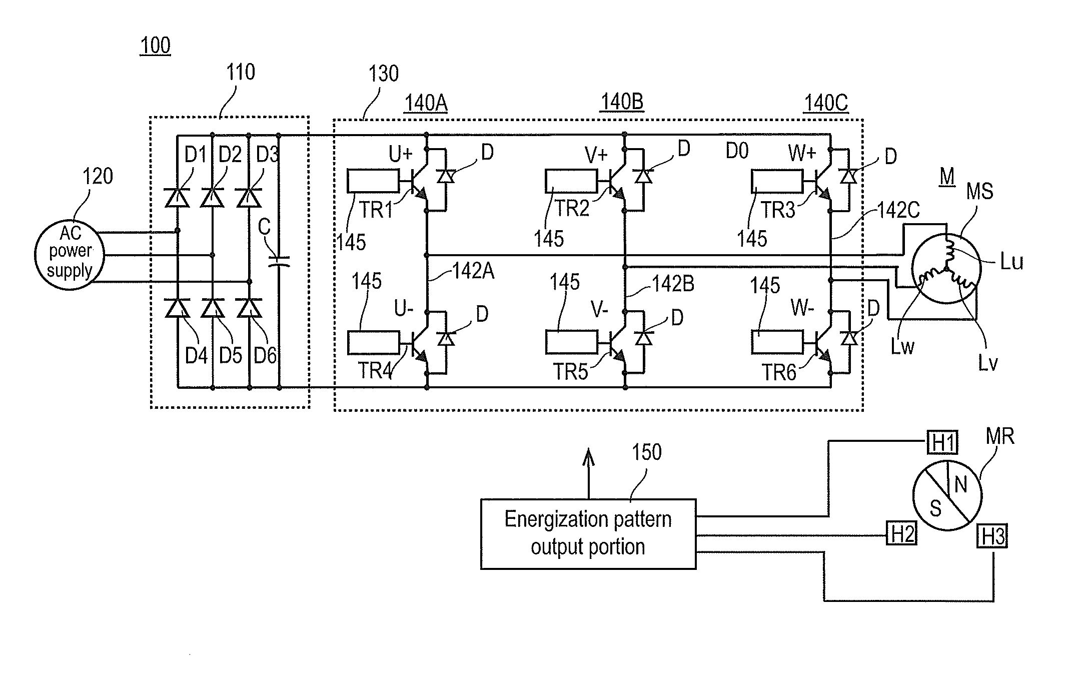
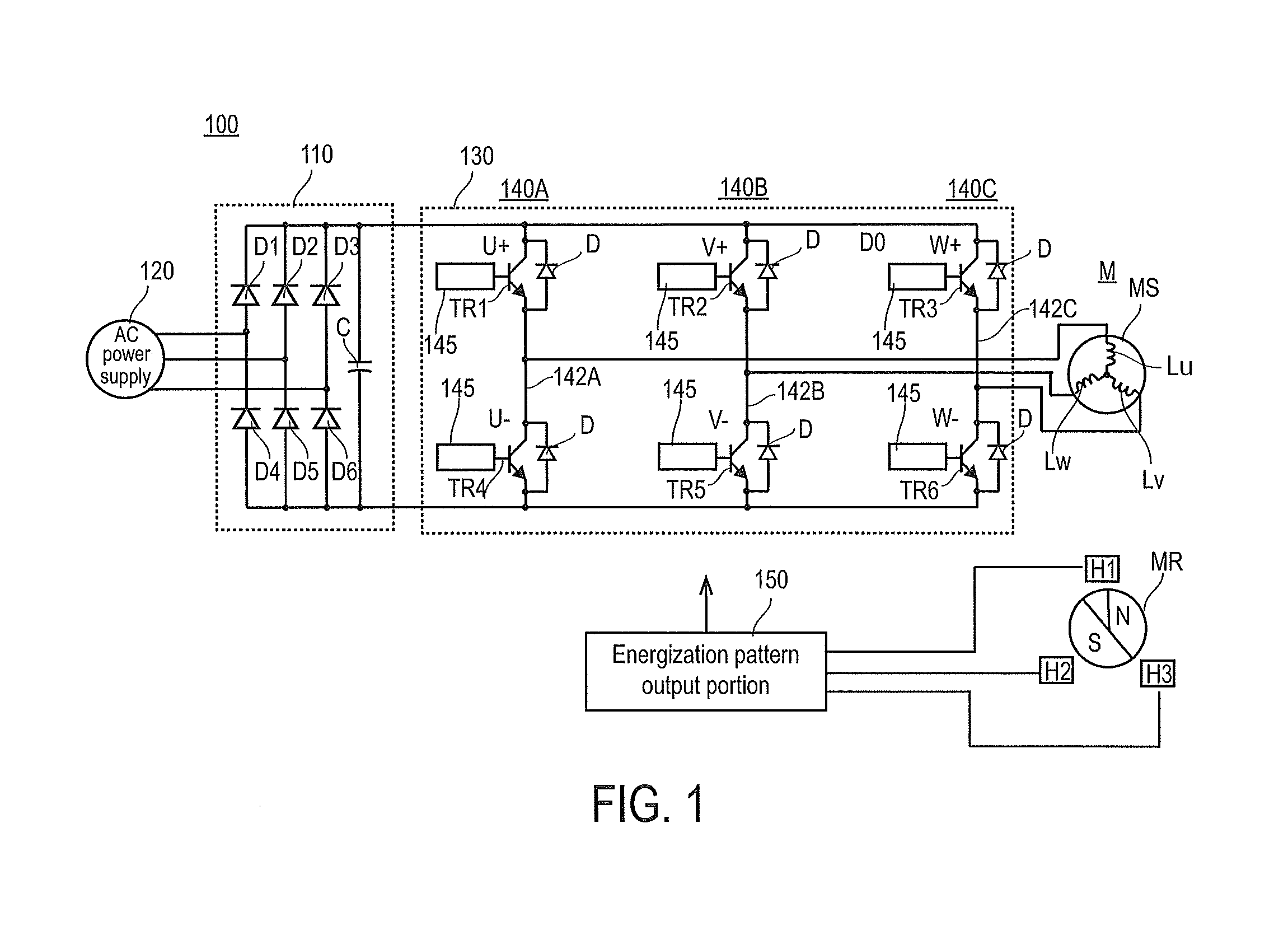
[0027]FIG. 1 illustrates a structure of a motor control device according to an embodiment.

[0028]A motor control device 100 includes a rectifier circuit 110 provided with a smoothing capacitor C and an inverter circuit 130 connected to a motor M.

[0029]The rectifier circuit 110 includes six bridge-connected diodes D1-D6 as illustrated in the figure, and the six diodes D1-D6 perform full-wave rectification on a current flowing from an AC (3-phase) power supply 120. The smoothing capacitor C smoothes the current subjected to the full-wave rectification by the six diodes D1-D6 so that the ripple in the DC current subjected to the full-wave rectification decreases. The rectifier circuit 110 is a power supply of the motor M.

[0030]The inverter circuit 130 is connected in parallel to the rectifier circuit 110. The inverter circuit 130 in...


PUM


Abstract

A motor control device includes an energization pattern output portion and an inverter circuit. The energization pattern output portion cyclically outputs a plurality of energization patterns. The inverter circuit selectively connects respective coils provided in a motor to a rectifier circuit according to the output energization pattern. The energization pattern output portion delays the output timing of the energization pattern according to a rotation speed of the motor.

Description

BACKGROUND[0001]1. Technical Field[0002]The present invention relates to a motor control device and a motor control method which can optimize efficiency according to a rotation speed of an electric motor.[0003]2. Description of Related Arts[0004]In the past, a brushless motor that allows speed control in a wide range has been used as a fan motor. As described in JP 2002-191186 A described below, the brushless motor includes a plurality of Hall elements, and detects a rotation position of a rotor, using a signal output from the Hall elements.[0005]The energization pattern of the stator coils in the brushless motor is determined according to a rotation position of the rotor. The energization pattern is a pattern indicating the stator coil connected to the power supply according to the rotation position of the rotor as well as a direction of the current that flows through the stator coil connected to the power supply. The stator coils are energized according to a predetermined energiza...

Claims


Application Information

Patent Timeline
Patent Type & Authority Applications(United States)
IPC IPC(8): H02P6/14H02P6/06H02P6/08H02P6/17H02P27/06H02P27/08
CPCH02P6/145H02P6/14H02P27/08H02P6/153Y02P80/10
Inventor MURAMATSU, YOTODA, TAKAHISA
Owner SANYO DENKI CO LTD
Why Eureka
Try Eureka