Front light module

a front light and module technology, applied in the field of light source modules, can solve the problems of reducing insufficient brightness, and often non-uniform light, and achieve the effects of improving the comfortability of use, reducing the difficulty of use, and improving the refraction

Inactive Publication Date: 2014-03-06
KUO HENG SHENG
View PDF3 Cites 2 Cited by
  • Summary
  • Abstract
  • Description
  • Claims
  • Application Information

AI Technical Summary

Benefits of technology

[0008]Another objective of the present invention is to provide a front light module, wherein the light guide plate has a plurality of microstructures disposed on a side parallel to the intermediate layer. With the installation of the front light module of the present invention, vaguely seen marks of the microstructures can be avoided to enhance the comfortability of the use.
[0009]Compared with the prior art, an intermediate layer is filled and distributed in the microstructures of the light guide plate of the front light module of the present invention. Since the intermediate layer is made of water, colloid or silicone, therefore better refraction and light guide effect can be achieved when the light passes through the intermediate layer, and the light can be uniformly and wholly reflected and refracted to the panel to provide sufficient brightness, enhance the uniformity and brightness of the panel, and improve the applicability of the present invention.

Problems solved by technology

However, glare, insufficient brightness, or non-uniform light often occurs during the use of the conventional front light module.
However, users still can vaguely see the existence of the marks of the microstructures, which will reduce the comfortability of the use.

Method used


Image

  • Front light module
  • Front light module
  • Front light module

Examples


Embodiment Construction

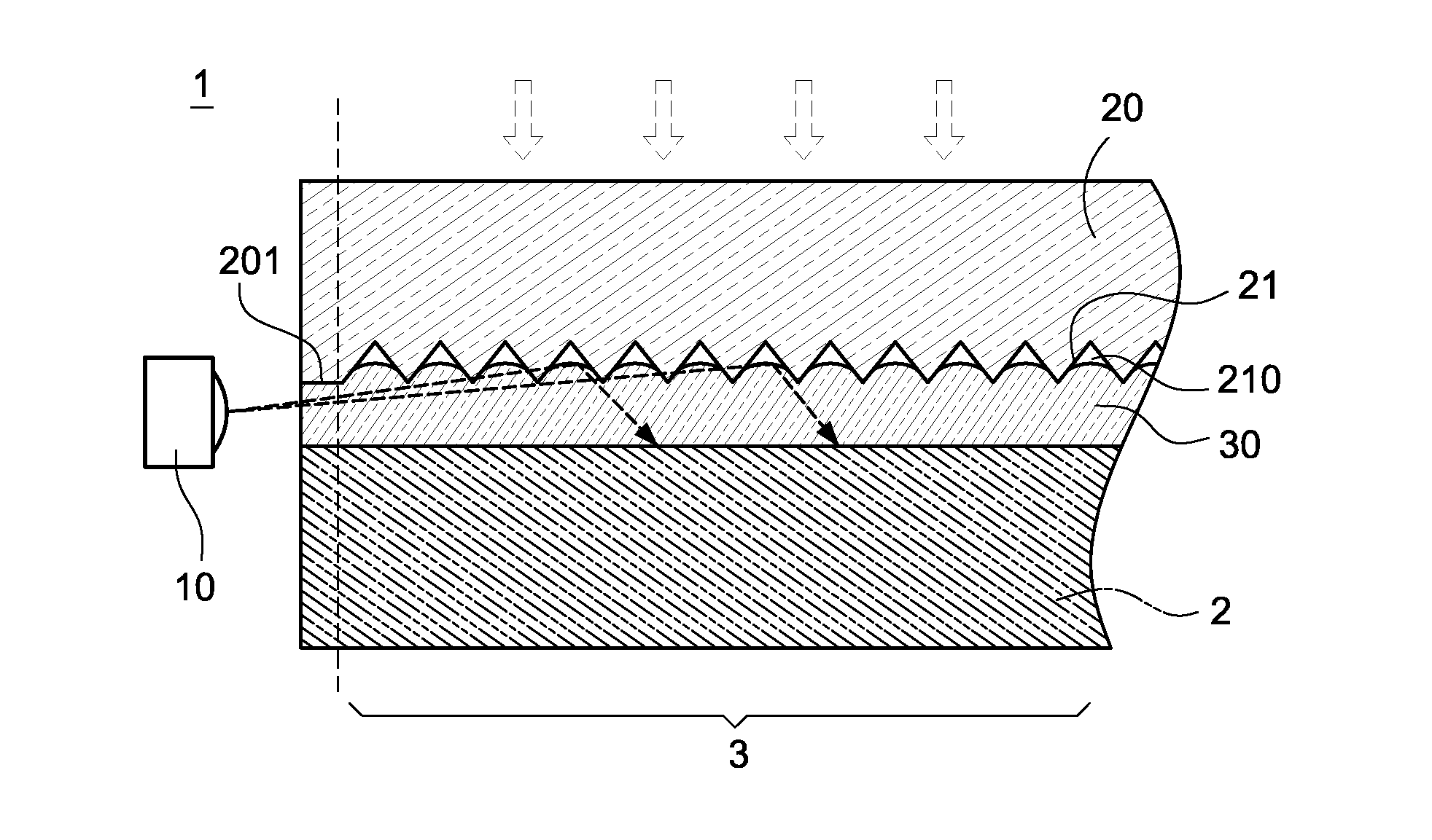
[0013]The technical contents of the present invention will become apparent with the detailed description of preferred embodiments accompanied with the illustration of related drawings as follows. It is noteworthy that the drawings are provided for the purpose of illustrating the present invention, but not intended for limiting the scope of the invention.

[0014]With reference to FIG. 1 for a cross-sectional view of a front light module of the present invention, the front light module 1 is installed in front of a panel 2, and the panel 2 has a viewing area 3. The front light module 1 comprises a light source 10, a light guide plate 20, and an intermediate layer 30, wherein the light source 10 is disposed on a side of the light guide plate 20 and the intermediate layer 30.

[0015]The light source 10 is an optical diode including but not limited to a light emitting diode (LED) or a laser diode (LD), and the light source 10 is can be a light source of a cold cathode tube.

[0016]The light gui...


PUM


Abstract

A front light module is installed in front of a panel, and the front light module includes a light source, a light guide plate and an intermediate layer disposed on an external side of the panel, and the light guide plate is provided for receiving a light emitted from the light source and reflecting and refracting the light onto the panel, and the light guide plate has a plurality of microstructures disposed on at least one side parallel to the panel, and the intermediate layer is filled and distributed in the microstructures, so as to avoid glare and enhance the brightness and uniformity of the panel.

Description

FIELD OF THE INVENTION[0001]The present invention relates to a light source module, in particular to a front light module.BACKGROUND OF THE INVENTION[0002]In general, most display panels require a light source module for providing sufficient brightness and distributing a light source uniformly, so as to achieve a uniform, high-brightness and wide-angle display effect. If the light source module is installed at a position in front of a glass display device, the light source module is called a front light module.[0003]The front light module is a product that converts a point or line light source into a plane light source with uniform brightness by a light guide structure. In daytime or an environment with sufficient illuminations, the front light module can use an external light source to provide a uniform brightness. In an environment with insufficient external light sources, the front light module immediately turns on its light source to maintain a normal display of images from the ...

Claims


Application Information

Patent Timeline
Patent Type & Authority Applications(United States)
IPC IPC(8): F21V8/00
CPCG02F1/133502G02F1/133615G02F1/133616
Inventor KUO, HENG-SHENG
Owner KUO HENG SHENG
Why Eureka
Try Eureka