Memory material implant system and methods of use

a memory material and implant system technology, applied in the field of orthopedics, can solve the problems of traumatic implantation of internal fixation or fusion devices, adverse impact on healing process, revision surgery or on-going pain experienced by patients, etc., and achieve the effect of reducing the possibility of implant migration and adding structural rigidity

Inactive Publication Date: 2014-03-06
HAUCK BRIAN ALBERT
View PDF6 Cites 108 Cited by
  • Summary
  • Abstract
  • Description
  • Claims
  • Application Information

AI Technical Summary

Benefits of technology

[0011]The claimed invention is directed to systems and methods for fixating or fusing bones that have an original shape that can be configured to deform into shapes that have circumferential lengths that remain substantially unchanged, and when inserted into the body returns to an

Problems solved by technology

The implantation of internal fixation or fusion devices can often be traumatic.
If insufficient stabilization or incorrect anatomical alignment occurs, then revision surgery or on-going pain may be experienced by the patient.
Osteoblast is believed to promote or accelerate the healing process and by flushing it away there may be a detrimental impact to the healing process.
Cheung et al includes bone fixation without using other fastening elements but does not provide a method for maintaining the device in a chilled martensitic phase during implantation.
However this device does not define any means for mechanical fixation.
Other attempts such as U.S. Pat. No. 8,162,9

Method used


Image

  • Memory material implant system and methods of use
  • Memory material implant system and methods of use
  • Memory material implant system and methods of use

Examples


second embodiment

[0048]According to one embodiment of the invention, a nitinol implant system 1700 is treated thermally and mechanically such that it has one predetermined memory set shape. The implant system can be provided with one-way shape memory such that it can undergo deformation at a relatively cool temperature and then recover its preset memory shape upon heating above its austenite finish transformation temperature without requiring external mechanical forces. In a second embodiment, the implant system can be provided with two-way shape memory where the device has a shape that is reversible upon return of the temperature.

third embodiment

[0049]In a third embodiment, the implant system 400 / 2000 may rely on the materials super-elastic properties. For embodiments incorporating the use of super-elastic properties, the implant system is deformed and constrained in the deformed shape using a rigid mandrel. The rigid mandrel may be comprised of a rod or tube. The preferred embodiment would be comprised with the rigid mandrel tube being sized to fit within the inner diameter of the implant system. The inner diameter of the rigid mandrel tube being sized to fit over a guide wire.

[0050]According to one embodiment of the invention, the implant system 1700 can have a memory shape to which it returns when, for example, its temperature is increased to about an average body temperature after having been cooled below its austenite start temperature. The implant system for example, can be designed so that when cooled below about 5° C. it is in its martensitic state and when warmed above about 30° C. it returns to its austenitic stat...

first embodiment

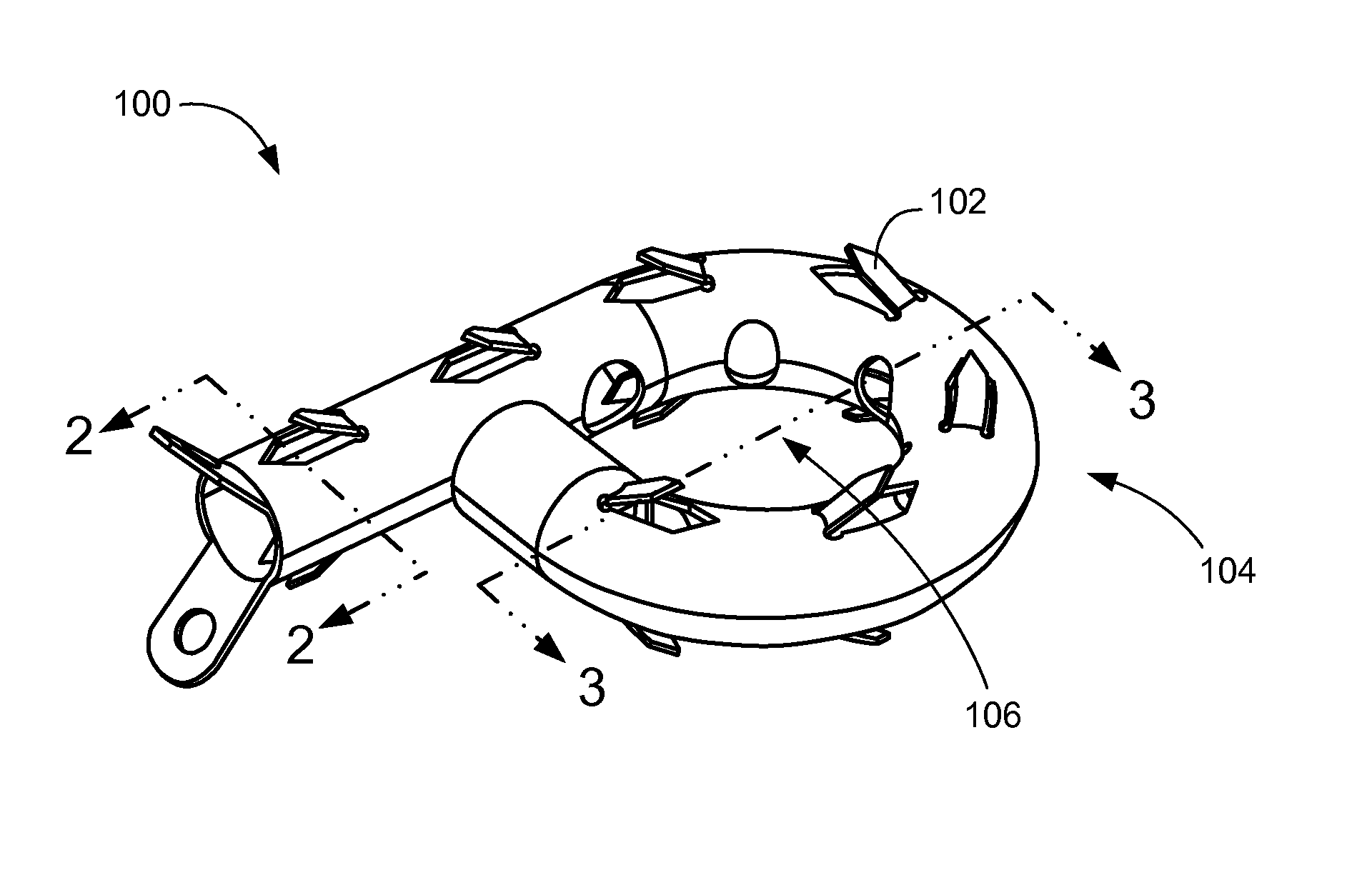
[0055]Referring now to FIG. 1, therein is shown an isometric view of an implant system 100 in the present invention and in an original shape 104. In this embodiment, the implant has barbs 102 that extend radially outward from the main body of the implant system 100. Implant systems 100 for spine fusion will typically take on a general “p” shape configuration when in the original shape 104. The center 106 of the “p” configuration can act as a receptacle for bone graft or other osteogenic material. This receptacle region provides the benefit of containing or limiting the migration of the osteogenic material.

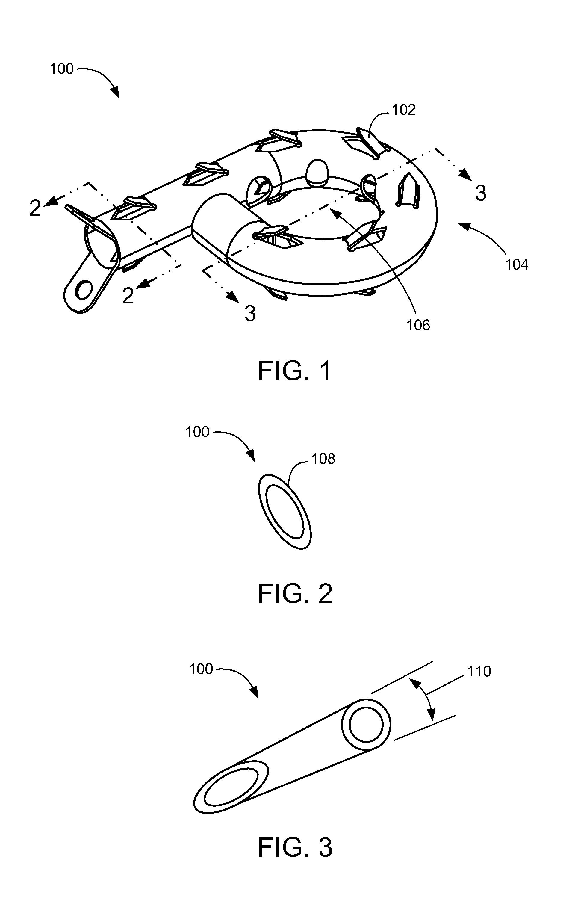
[0056]Referring now to FIG. 2, therein is shown a cross-sectional view of the implant system 100 of FIG. 1 along the line 2-2. This cross-section shows how the original shape 104 of FIG. 1 of the implant system 100 has been set such that it forms an ellipse 108 with the major axis in the horizontal plane and the minor axis in the vertical plane.

[0057]Referring now to FIG. 3, therei...


PUM

PropertyMeasurementUnit
Lengthaaaaaaaaaa
Shapeaaaaaaaaaa

Abstract

Apparatus and method used to reduce the movement between vertebrae or fractured bones. The implantable device can be deformed from its shape-set configuration for ease of deployment and return to a pre-set shape upon completion of deployment. The apparatus can serve to stabilize fractured bones or as a distraction device and support structure between vertebrae. Device may be made of a material with shape memory and superelastic properties which facilitate the method of implantation. The pre-set shape of the device may include dimensions/geometries which are similar to the natural curvature of the human spine or bone without the use of hinging or connection between multiple pieces. Once deployed, the device can serve to constrain the flow of bone growth material between the inside and outside of the device.

Description

CROSS-REFERENCE TO RELATED APPLICATIONS[0001]This is a Continuation-In-Part of U.S. patent application Ser. No. 13 / 964,039 filed Aug. 9, 2013, which claims the benefit of priority to U.S. Provisional Patent Application 61 / 682,282 filed Aug. 12, 2012, and priority benefit is claimed for all common subject matter thereof. The benefit of priority is further claimed, for all common subject matter, to U.S. Provisional Patent Application 61 / 837,703 filed Jun. 21, 2013. The benefit of priority is further claimed, for all common subject matter, to U.S. Provisional Patent Application 61 / 725,030 filed Nov. 10, 2012. Each of which are incorporated herein by reference in their entirety.STATEMENT REGARDING FEDERALLY SPONSORED RESEARCH OR DEVELOPMENT[0002]Not ApplicableREFERENCE TO SEQUENCE LISTING, A TABLE, OR A COMPUTER PROGRAM LISTING COMPACT DISK APPENDIX[0003]Not ApplicableFIELD OF THE INVENTION[0004]The application relates to orthopedics and more particularly to bone fixation and spinal fus...

Claims


Application Information

Patent Timeline
IPC IPC(8): A61F2/44A61B17/88A61B17/72
CPCA61F2/4455A61B17/8825A61B17/7266A61F2/4465A61F2/4611A61F2002/2817A61F2002/2835A61F2002/30092A61F2002/30116A61F2002/302A61F2002/30235A61F2002/30462A61F2002/30545A61F2002/3055A61F2002/30555A61F2002/30576A61F2002/30578A61F2002/30583A61F2002/30588A61F2002/30841A61F2002/30845A61F2310/00023A61F2310/00796A61F2310/00017A61F2/30
Inventor HAUCK, BRIAN ALBERT
Owner HAUCK BRIAN ALBERT
Why Eureka
Try Eureka