In-situ robotic inspection of components

a robotic inspection and component technology, applied in the field of turbines, can solve the problems of inability to detect cracks, unreliable visual inspection, and degrade protective thermal coatings, and achieve the effects of reducing the safety of workers, and reducing the risk of damag

Inactive Publication Date: 2014-03-06
GENERAL ELECTRIC CO
View PDF3 Cites 17 Cited by
  • Summary
  • Abstract
  • Description
  • Claims
  • Application Information

AI Technical Summary

Problems solved by technology

During operation of a turbomachine (e.g., a gas turbine), components within that turbine (e.g., rotor and stator blades) are exposed to high pressures and temperatures, which can cause the protective thermal coatings to degrade and spall and cracks to form in the components.
Visual inspections of components can be done, but visual inspection is unreliable, and cannot detect cracks that have no surface opening (i.e., closed cracks) or delaminations of the coatings.
Even when a visible crack with a surface opening (i.e., an open crack) is detected, it is not possible to quantify depth of the crack using visual inspection.
In addition, unless there is an obvious spallation of the coatings their health is difficult to judge.

Method used


Image

  • In-situ robotic inspection of components
  • In-situ robotic inspection of components
  • In-situ robotic inspection of components

Examples


Embodiment Construction

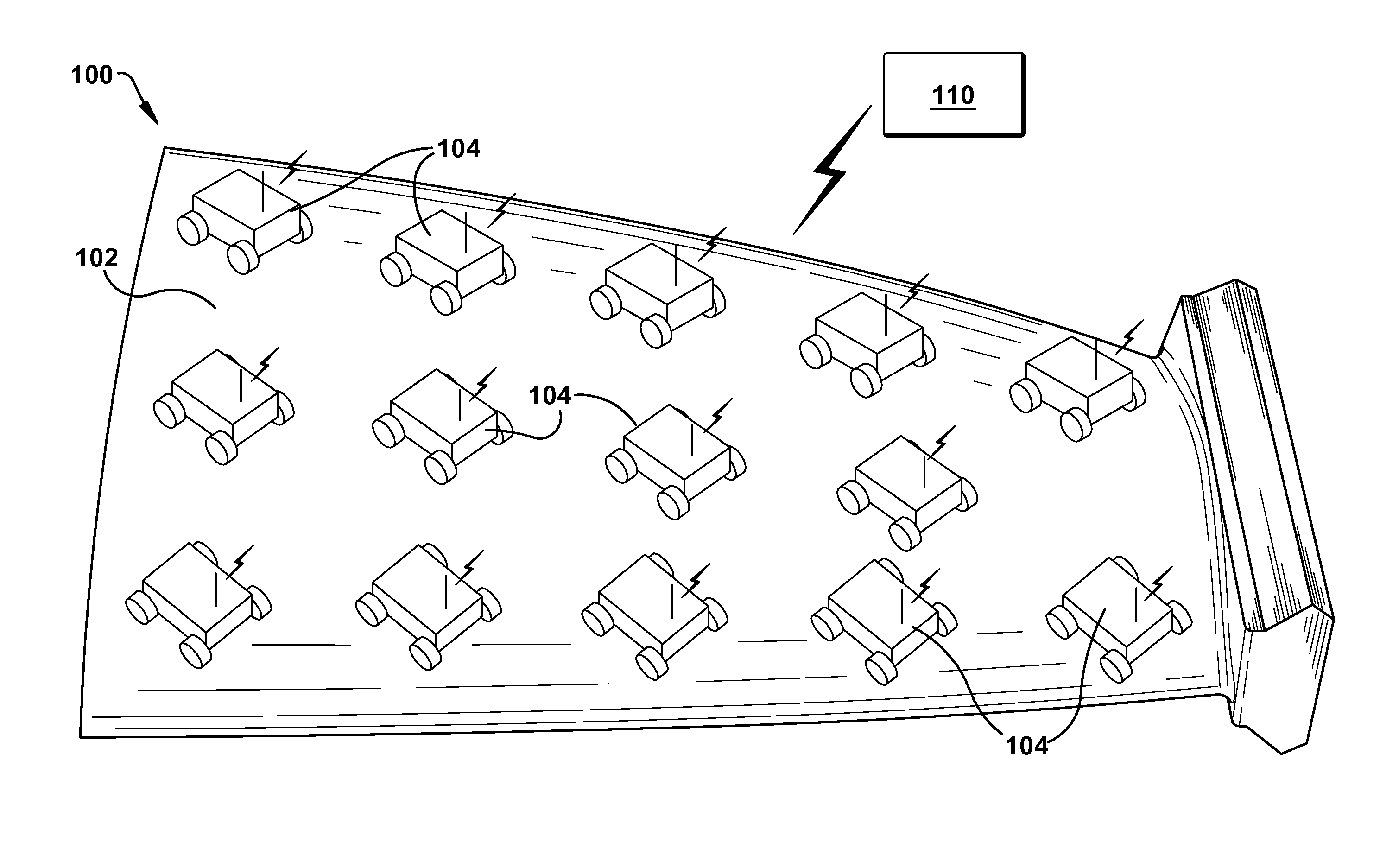
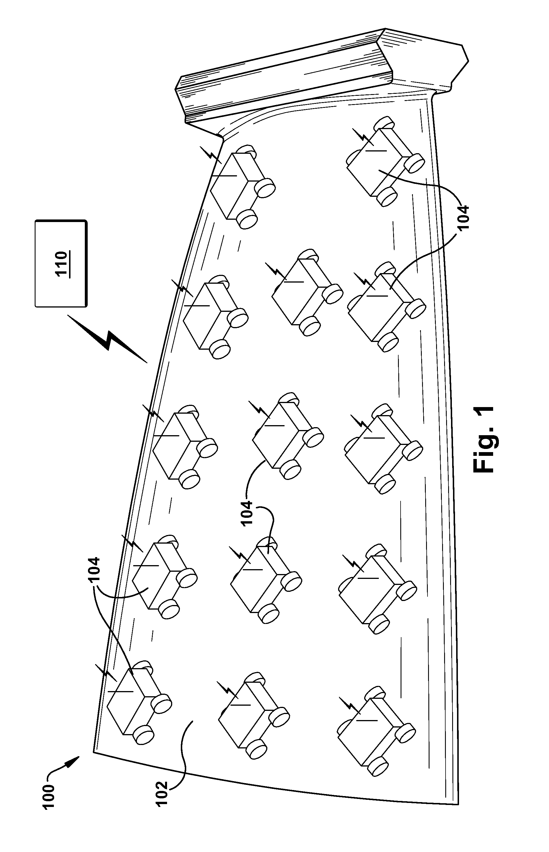
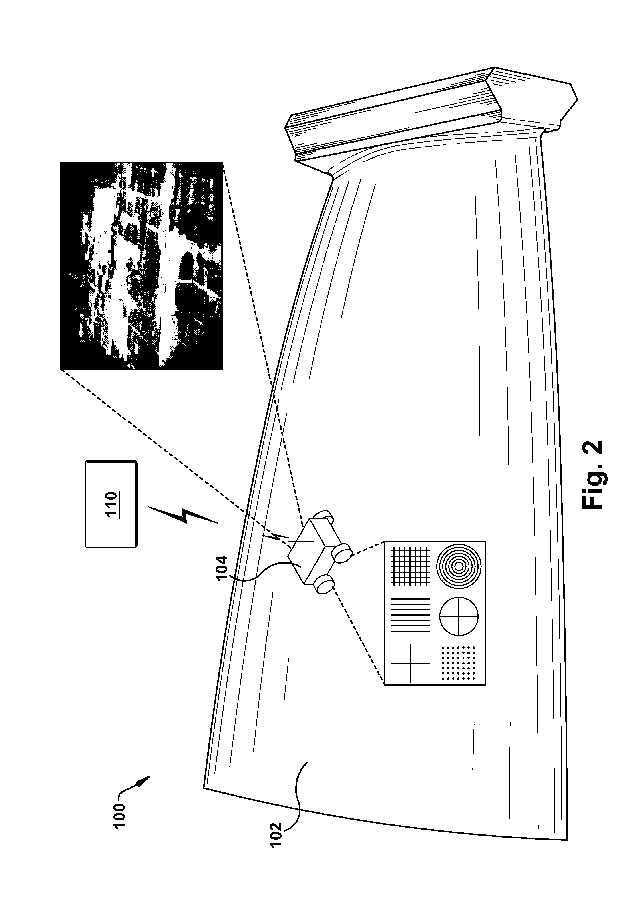
[0014]Systems for inspecting surfaces of components in-situ within a turbomachine, e.g., blades or vanes, are disclosed. As discussed in more detail herein, in one embodiment, structured infrared (IR) light is created, e.g., multiple lines using programmable light emitting diodes (LEDs), and a cooled IR focal plane detector chip can then image surface temperature as a function of time. Multiple robots with LED driven sources and IR detectors can be spread out over the surface area of interest, enabling full coverage. The thermal images can be converted into time-of-flight maps and temperature maps at a specific critical time, synchronized with IR LEDs on-off triggers. These images can give a direct indication of a defect size. Comparison can then be carried out with optical images. The resulting fused images directly supply quantitative defect information.

[0015]Turning to FIG. 1, one embodiment of the invention is shown. System 100 is shown in use inspecting a blade 102. As known in...


PUM

PropertyMeasurementUnit
heataaaaaaaaaa
thermalaaaaaaaaaa
ultrasonic testingaaaaaaaaaa

Abstract

Methods and systems for inspecting a component within an assembled turbomachine are disclosed. At least one miniature robotic device having a non-destructive testing structure attached thereto is configured to travel around a surface of the component. The non-destructive testing structure gathers data related to the surface, and sends the data to a computing device connected to the at least one miniature robotic device. In one embodiment, the non-destructive testing structure comprises an image capture device and an infrared (IR) heat source.

Description

FIELD OF THE INVENTION[0001]The subject matter disclosed herein relates to turbines. More particularly, aspects of the disclosure relate to systems for in-situ inspection of components in a turbine using robotic infrared (IR) thermography and / or other miniaturized inspection methods.BACKGROUND OF THE INVENTION[0002]During operation of a turbomachine (e.g., a gas turbine), components within that turbine (e.g., rotor and stator blades) are exposed to high pressures and temperatures, which can cause the protective thermal coatings to degrade and spall and cracks to form in the components. Early detection of crack formation and coating health are desirable so that suitable measures can be initiated to fix or replace components, before serious consequences occur.[0003]Visual inspections of components can be done, but visual inspection is unreliable, and cannot detect cracks that have no surface opening (i.e., closed cracks) or delaminations of the coatings. Even when a visible crack with...

Claims


Application Information

Patent Timeline
Patent Type & Authority Applications(United States)
IPC IPC(8): G05D1/02G01N23/02G01R33/12G01N29/04H01L27/146
CPCG01R33/12G01N27/90G01N29/043G01N2291/2693B23P6/002
Inventor TRALSHAWALA, NILESHKNIGHT, BRYON EDWARDRINGERMACHER, HARRY ISRAEL
Owner GENERAL ELECTRIC CO
Why Eureka
Try Eureka