
Expert system for prediction of changes to local environment

Active Publication Date: 2014-03-06
KINESTRAL TECH
View PDF0 Cites 107 Cited by
  • Summary
  • Abstract
  • Description
  • Claims
  • Application Information

AI Technical Summary

Benefits of technology

The present invention involves various embodiments that can be used alone or together with each other in any combination. These embodiments address different deficiencies that were previously present in the prior art. The invention has various features, benefits, and advantages that will be apparent upon review of the present disclosure.

Problems solved by technology

Some embodiments may only partially address some deficiencies or just one deficiency that may be discussed in the specification, and some embodiments may not address any of these deficiencies.

Method used


Image

  • Expert system for prediction of changes to local environment
  • Expert system for prediction of changes to local environment
  • Expert system for prediction of changes to local environment

Examples


Embodiment Construction

[0022]Embodiments of the present invention provide a system and method for a system and method for measurement and accurate prediction of sky / weather influence on building systems that respond to sky-related environment changes. The following description is presented to enable one of ordinary skill in the art to make and use the invention and is provided in the context of a patent application and its requirements.

[0023]Various modifications to the preferred embodiment and the generic principles and features described herein will be readily apparent to those skilled in the art. Thus, the present invention is not intended to be limited to the embodiment shown but is to be accorded the widest scope consistent with the principles and features described herein.

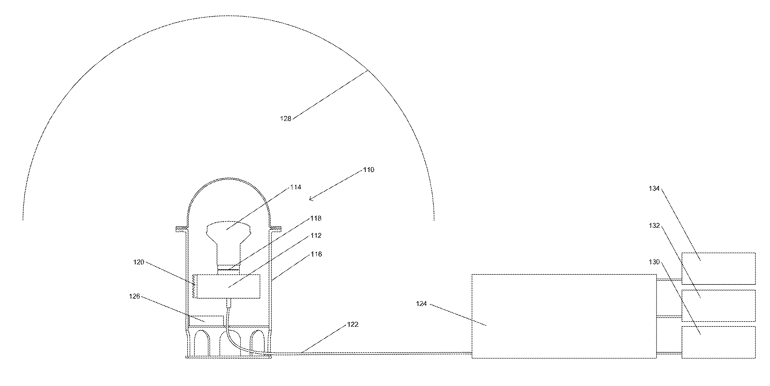
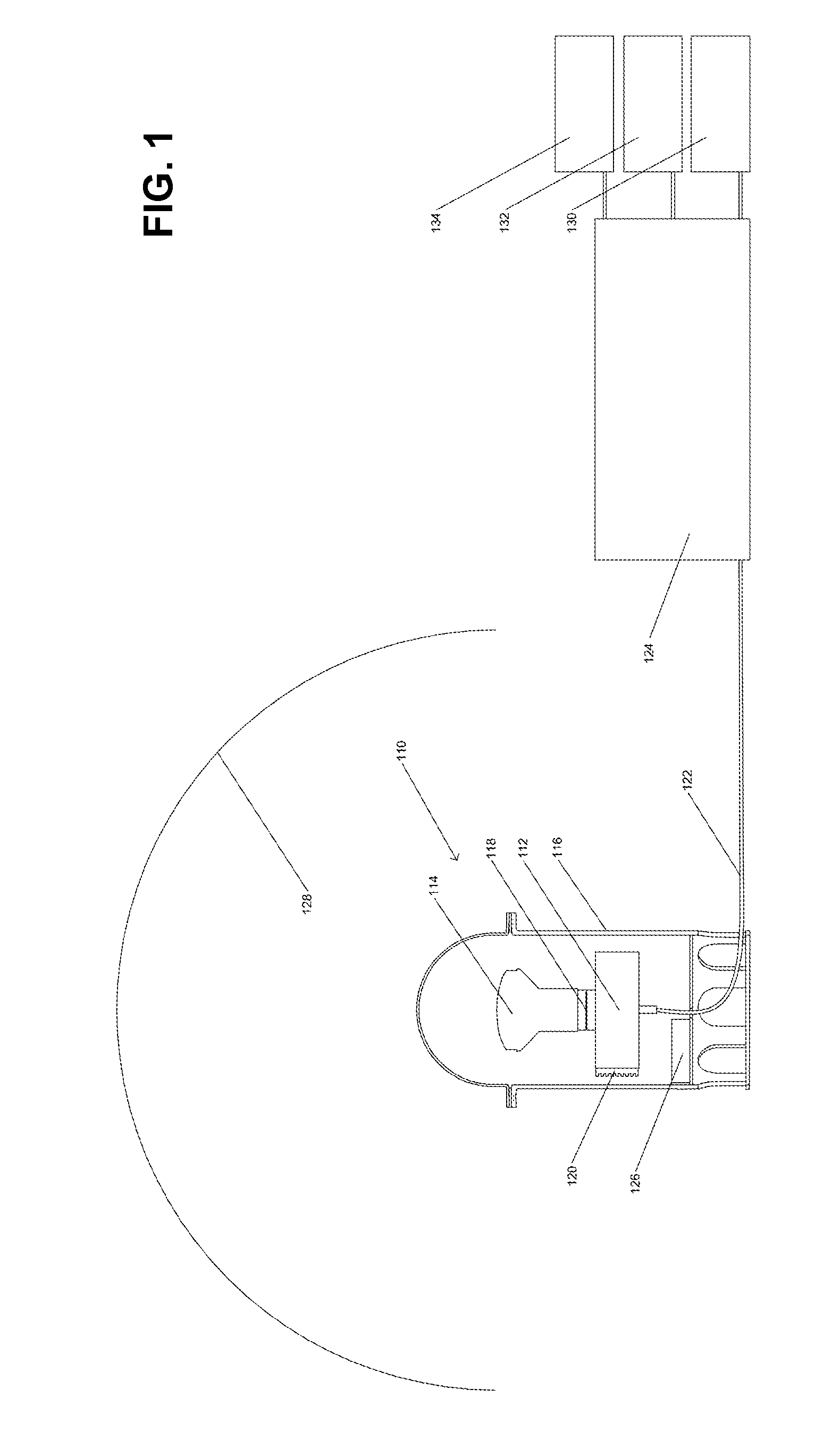
[0024]One embodiment of the HDR photometer system 110 is illustrated in FIG. 1 (section view). As depicted therein, the broad aspects of the embodiment 110 includes at least one interchangeable camera 112 capable of capturing a seq...


PUM


Abstract

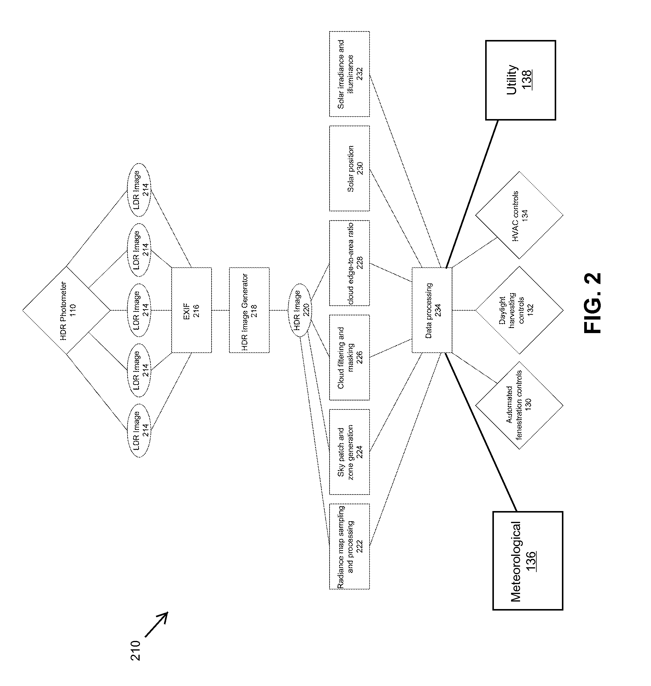
Disclosed is a photometer that employs high dynamic range (HDR) image processing and manipulation algorithms for capturing and measuring real-time sky conditions for processing into control input signals to a building's automated fenestration (AF) system, daylight harvesting (DH) system and HVAC system. The photometer comprises a color camera and a fitted fish-eye lens to capture 360-degree, hemispherical, low dynamic range (LDR) color images of the sky. Both camera and lens are housed in a sealed enclosure protecting them from environmental elements and conditions. In some embodiments the camera and processes are controlled and implemented by a back-end computer.

Description

CROSS REFERENCE TO RELATED APPLICATIONS[0001]This application claims benefit of U.S. Application No. 61 / 696,052 filed 31 Aug. 2012, the contents of which is hereby expressly incorporated in its entirety for all purposes.BACKGROUND OF THE INVENTION[0002]The present invention relates generally to a building automation control system, and more specifically, but not exclusively, to use of a high dynamic range (HDR) sky map for predictive control.[0003]This disclosure relates to a photometric device controlled wirelessly or directly by a microcontroller and / or a back-end computer system to control a building's automated daylighting fenestration system.[0004]The subject matter discussed in the background section should not be assumed to be prior art merely as a result of its mention in the background section. Similarly, a problem mentioned in the background section or associated with the subject matter of the background section should not be assumed to have been previously recognized in t...

Claims


Application Information

Patent Timeline
IPC IPC(8): G06N99/00G06N20/00
CPCG06N99/005G05B13/02F24F11/30F24F2110/00F24F2130/20F24F2130/00F24F2130/10F24F11/62F24F11/65G06N20/00F24F11/46F24F11/63G05B13/028G06N5/046G06N5/04
Inventor HUMANN, CHRISTIAN
Owner KINESTRAL TECH
Learn More