Method and system for clock offset and skew estimation

Active Publication Date: 2014-03-06
BRITISH TELECOMM PLC +2
View PDF5 Cites 49 Cited by
  • Summary
  • Abstract
  • Description
  • Claims
  • Application Information

AI Technical Summary

Benefits of technology

[0044]A further exemplary aspect of the present invention provides a time client communicably coupled to a time server over a network, the time client comprising: a local clock; and a control unit, wherein the control unit is arranged to receive Sync and Delay_Req messages under the IEEE 1588 PTP carrying timestamps from the time server and to record the time of receipt of those messages according to the local clock and extract the timestamps, and to perform a recursive estimation using a Kalman filter process based on the extracted timestamps and the output of the local clock to estimate the offset and skew of the local clock compared to a clock in the time server, wherein the Kalman filter is applied to: the measurement equation: (T2,n−T1,n)−(T4,n−T3,n)=2θn+αn(T1,n+T4,n)+vn, wherein: θn and αn are respectively the offset and the skew of the local clock at point n, T1,n is the timestamp applied by the time server to the nth Sync message; T2,n is the time of receipt as recorded by the local clock on receipt of the nth Sync message; T3,n is the timestamp applied by the time client to the nth Delay_Req message; T4,n is the time of receipt as recorded by the master clock on receipt of the nth Delay_Req message; and vn is the measurement noise which is assumed to be zero mean Gaussian white noise with covariance Rn=E[vnvnT], and to the two-state dynamic model defined by:
[0045]A further exemplary embodiment of the present invention provides a networked tim

Problems solved by technology

Many of these works [16-27] are mostly academic and do not show how the clock synchronization (correction) is implemented and how the slave clock behaves.
With this migration the challenge of frequency and time synchronization has surfaced.
The problem with all these techniques is the non-realistic assumption that the two clocks differ only by an offset.
The reality however is that the slave clock, in addition to the offset, deviates in time as well due the skew problem which is an inherent problem with most clocks.
The problem with line-regression algorithms is that they are usually not robust to presence of large outliers and thus the robustness is only valid for certain PDV models (e.g. Gaussian).
One major drawback of these techniques is that they have been developed using

Method used


Image

  • Method and system for clock offset and skew estimation
  • Method and system for clock offset and skew estimation
  • Method and system for clock offset and skew estimation

Examples


Embodiment Construction

[0054]Accordingly, at its broadest, a first aspect of the present invention provides a method of estimating the offset and skew of a local clock using a recursive estimation technique.

[0055]A first aspect of the present invention preferably provides a method of estimating the offset and skew of a local clock in a time client compared with a remote master clock in a time server, the method including the steps of:

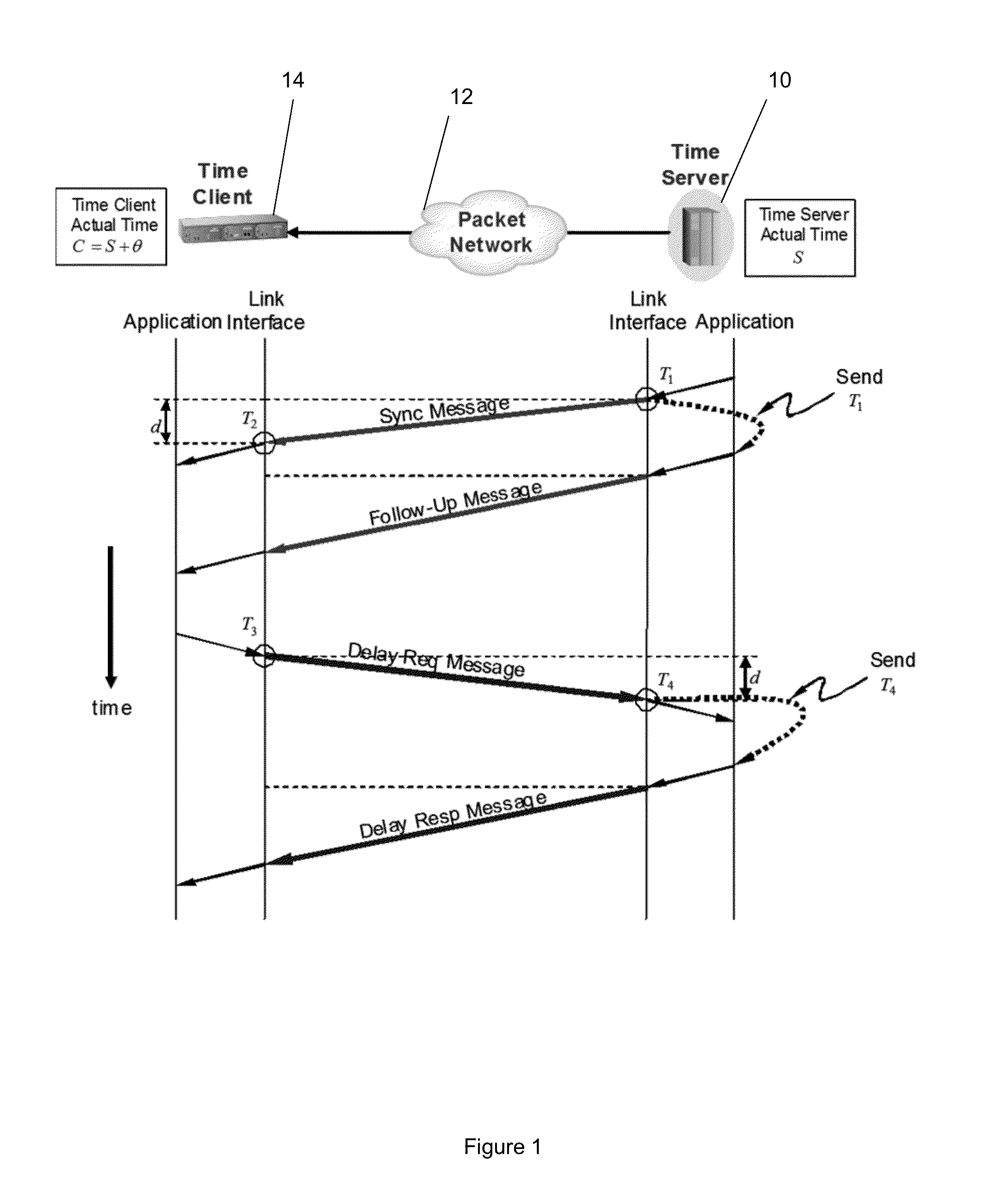
[0056]transmitting Sync and Delay_Req messages under the IEEE 1588 PTP, carrying timestamps from the time server;

[0057]receiving said messages at the time client and recording the time of receipt according to the local clock and extracting said timestamps; and

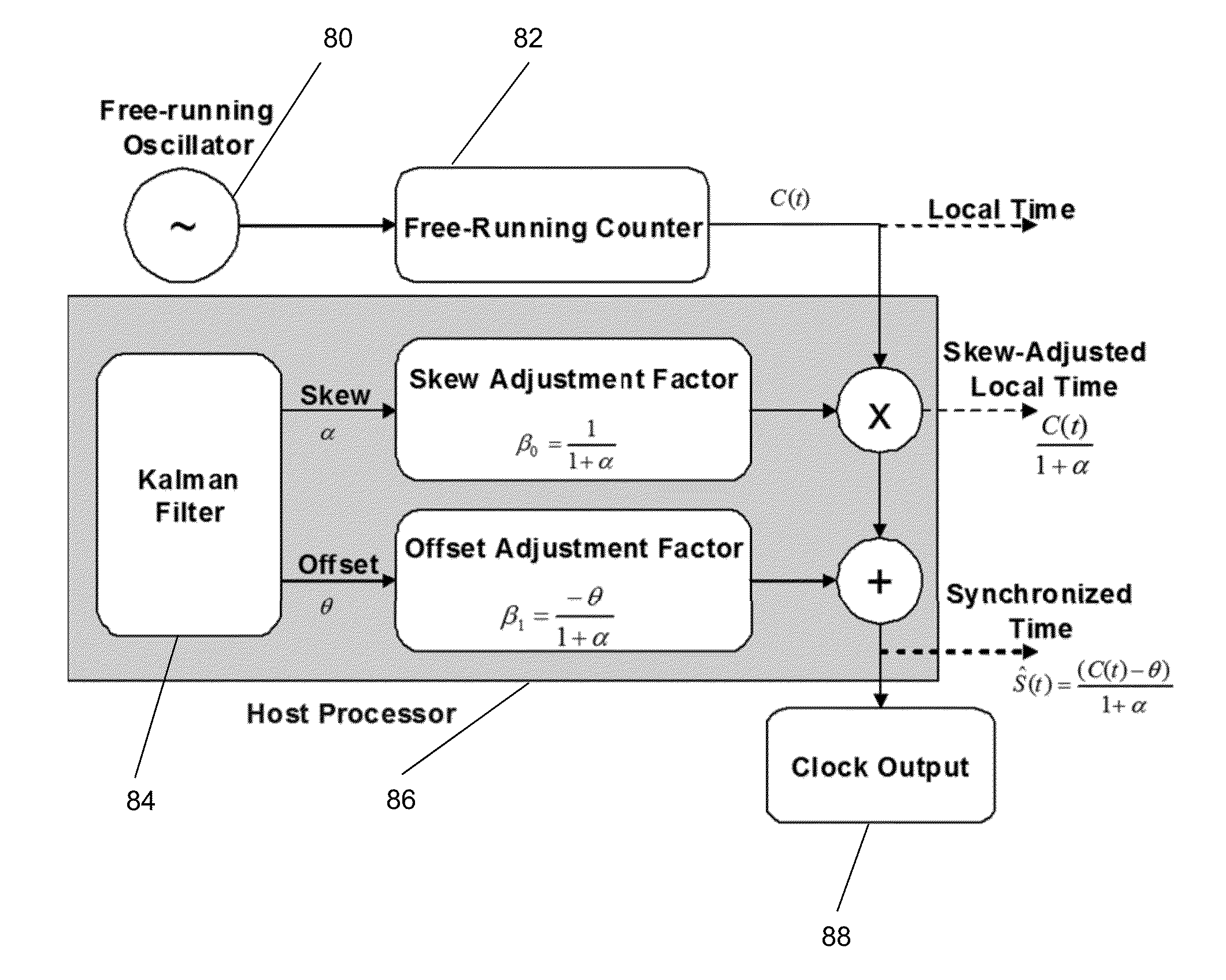
[0058]performing a recursive estimation using a Kalman filter process based on the extracted timestamps and the output of the local clock to estimate the offset and skew of the local clock compared to the master clock, wherein the Kalman filter is applied to:

[0059]the measurement equation:

(T2,n−T1,n)−(T4,n−T3,n)=2θn+αn(T...


PUM


Abstract

This invention relates to methods and devices for clock offset and skew estimation. The invention has particular application in the alignment of slave clocks to a master clock. In embodiments of the invention, the slave clock employs an independent free running clock and a recursive estimation technique to estimate the clock offset and clock skew between the slave and master clocks. The slave can then use the offset and skew to correct the free running clock to reflect an accurate image of the master clock.

Description

FIELD OF THE INVENTION[0001]The present invention relates to a method and system for clock offset and skew estimation. It is particularly, but not exclusively, concerned with the alignment of slave clocks to a master clock.BACKGROUND OF THE INVENTION[0002]IEEE 1588 Precision Time Protocol (PTP) [1][2] is the industry accepted protocol for transferring time information over packet networks. PTP is designed as an improvement to the current version of the Network Time Protocol (NTP) [3]. There are a number of works cited in the literature that describe clock synchronization using the Kalman filter technique. Many of these works [16-27] are mostly academic and do not show how the clock synchronization (correction) is implemented and how the slave clock behaves.BASIC DEFINITIONS[0003]Clock Offset: The clock offset at a particular moment is the difference between the time reported by the time client (slave) and the “true” time as reported by the time server (master).[0004]Clock Skew: A cl...

Claims


Application Information

Patent Timeline
IPC IPC(8): G06F1/04
CPCH04J3/0667G06F1/14H04L43/087G06F1/04
Inventor AWEYA, JAMESALSINDI, NAYEF
Owner BRITISH TELECOMM PLC
Why Eureka
Try Eureka