
Data recovery apparatus and method for minimizing errors due to clock skew

a data recovery and clock skew technology, applied in the field of data transmission systems, can solve problems such as difficult data recovery, parallel transmission channels, and errors in the portion at which the level of data is converted

Inactive Publication Date: 2005-10-25
SAMSUNG ELECTRONICS CO LTD
View PDF13 Cites 33 Cited by
  • Summary
  • Abstract
  • Description
  • Claims
  • Application Information

AI Technical Summary

Benefits of technology

[0008]It is another object of the present invention to provide a data recovery method for stably recovering data regardless of clock skew while receiving of data.

Problems solved by technology

However, problems may occur with this method of using the parallel transmission channels if the number of data transmission channels increases.
When serial data is converted to the parallel data format, it may be difficult to recover data due to clock skew at the receiving end.
With this method of determining data by detecting the generation frequency of data, however, errors may occur in a portion at which the level of data is converted due to the accumulation of clock skew.

Method used


Image

  • Data recovery apparatus and method for minimizing errors due to clock skew
  • Data recovery apparatus and method for minimizing errors due to clock skew
  • Data recovery apparatus and method for minimizing errors due to clock skew

Examples


Embodiment Construction

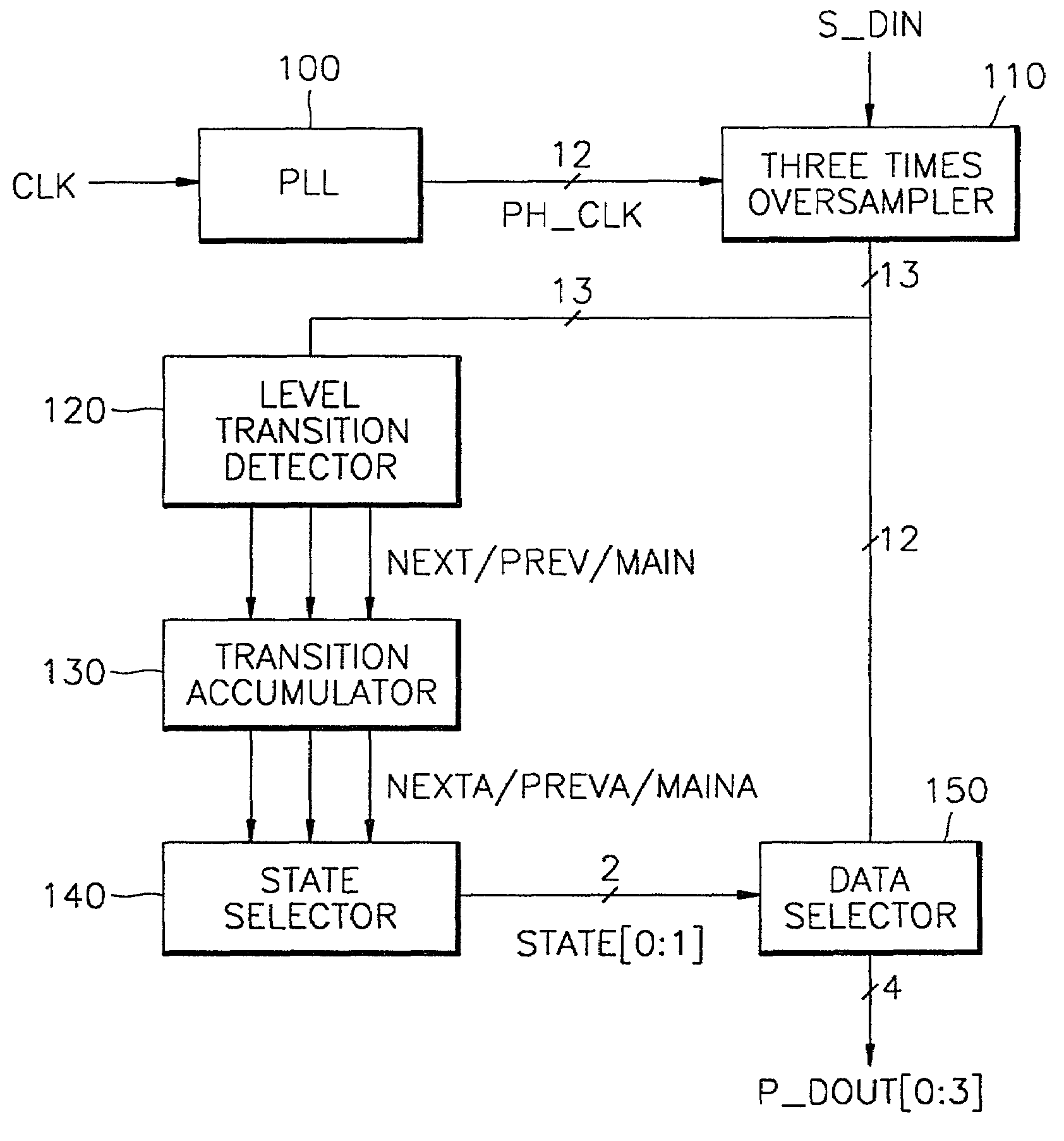
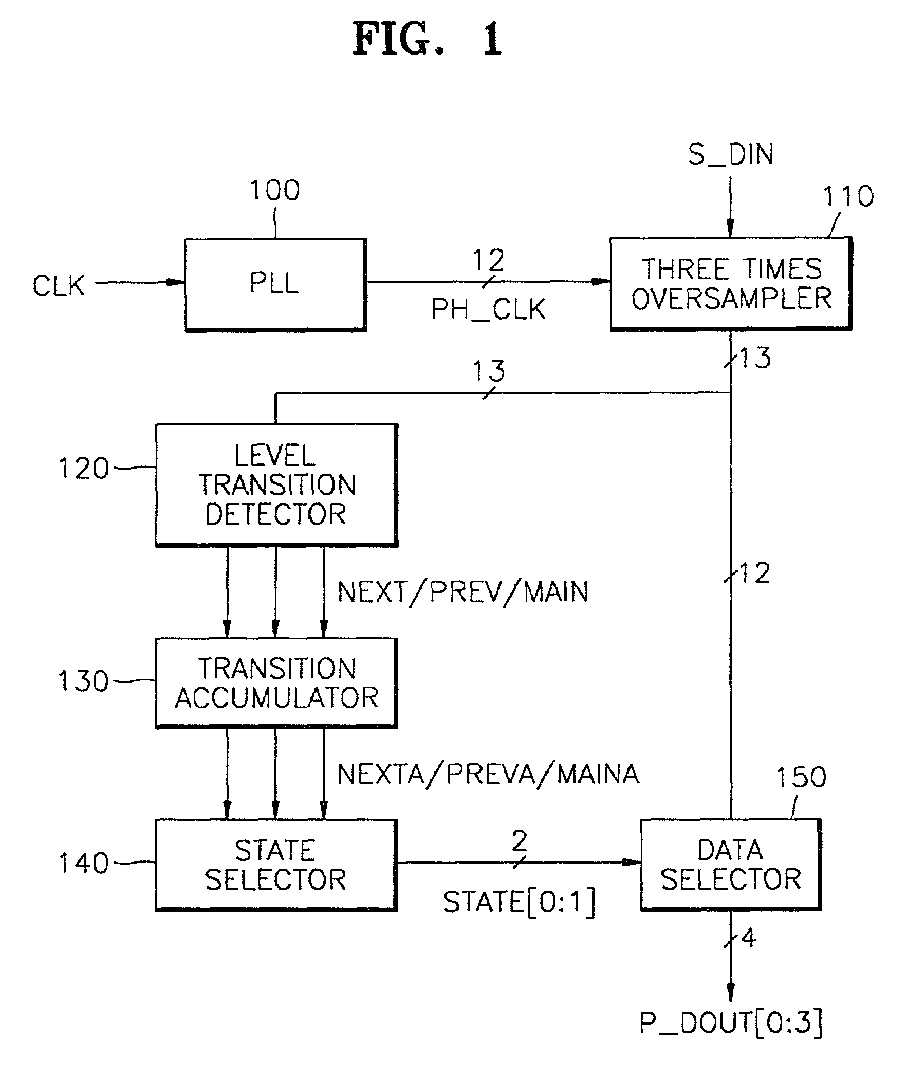
[0027]Referring now to FIG. 1, a block diagram illustrates a data recovery apparatus for minimizing errors due to clock skew according to an embodiment of the present invention. The data recovery apparatus comprises a phase locked loop (PLL) 100, a three-times oversampler 110, a level transition detector 120, a transition accumulator 130, a state selector 140, and a data selector 150.

[0028]The PLL100 generates a predetermined number of phase clock signals PH—CLK, which are synchronized with an input clock signal CLK. Here, each of the phase clock signals PH—CLK have different delay times with respect to the input clock signal CLK. In the embodiment of FIG. 1, it is assumed that the phase clock signals PH—CLK have twelve different delay times. The phase clock signals PH—CLK are received by the three-times oversampler 110 in parallel and are used as sampling clock signals.

[0029]The oversampler 110 three-times oversamples data S—DIN, which is serially input from an external source, in ...


PUM


Abstract

A data recovery apparatus for minimizing errors due to clock skew and a data recovery apparatus therefor are provided. The data recovery apparatus comprises a phase locked loop (PLL), an oversampler, a level transition detector, a transition accumulator, a state selector, and a data selector. The PLL generates a plurality of phase clock signals having different delay times, which signals are synchronized with an input clock signal. The oversampler 110 M (>1) times oversamples data serially input from the outside in response to the plurality of phase clock signals and outputs the oversampled result as a plurality of bit data items. The level transition detector receives the plurality of bit data output from the oversampler, detects the point of time at which the level transitions between adjacent bits and outputs the detection result as first through Mth transition signals. The transition accumulator accumulates the number of generations of the first through Mth transition signals output from the level transition detector and outputs a signal whose generation frequency is high as first through Mth transition accumulation signals. The state selector generates a state signal for selecting bit data items of corresponding positions among the plurality oversampling data items in response to the first through Mth transition accumulation signal. The data selector receives the oversampled plurality of bit data, selects bit data items of the sampling positions corresponding to the state signal, and outputs the selected bit data items in parallel. It is possible to minimize errors due to clock skew, which can be generated during the reproduction of data.

Description

BACKGROUND[0001]1. Technical Field[0002]The present invention relates generally to a data transmission system and, more particularly, to a data recovery circuit and method for minimizing errors due to clock skew.[0003]2. Description of Related Art[0004]In general, in a data transmission system for transmitting predetermined data, the use of parallel transmission channels is a popular method for digitally interfacing systems. However, problems may occur with this method of using the parallel transmission channels if the number of data transmission channels increases. Consequently, a serial transmission method is gradually replacing the parallel transmission method.[0005]With the serial transmission method, the number of channels used for transmitting data is less than the number of channels used for transmitting data using the parallel transmission method. However, in most cases, when data is transmitted using serial transmission channels, a high speed serial signal must be converted...

Claims


Application Information

Patent Timeline
Patent Type & Authority Patents(United States)
IPC IPC(8): H04L25/06H04L7/033H04L7/00G06F1/12H04N7/12
CPCH04L7/0338H04L25/068H04L25/069H04L7/0331H04L7/0337
Inventor YOO, DUCK-HYUNLEE, GUN-SANGLEE, JIN-KUG
Owner SAMSUNG ELECTRONICS CO LTD
Learn More