

Image diagnosis apparatus and power control method of an image diagnosis apparatus
a technology of image diagnosis and power control, which is applied in the direction of instruments, applications, measurement using nmr, etc., can solve the problems of limiting the design of the site, increasing the cost of the facility, and not knowing the uninterruptible power source described in the patent document 1
- Summary
- Abstract
- Description
- Claims
- Application Information
AI Technical Summary
Benefits of technology
Problems solved by technology
Method used
Image

Examples
first embodiment
The First Embodiment
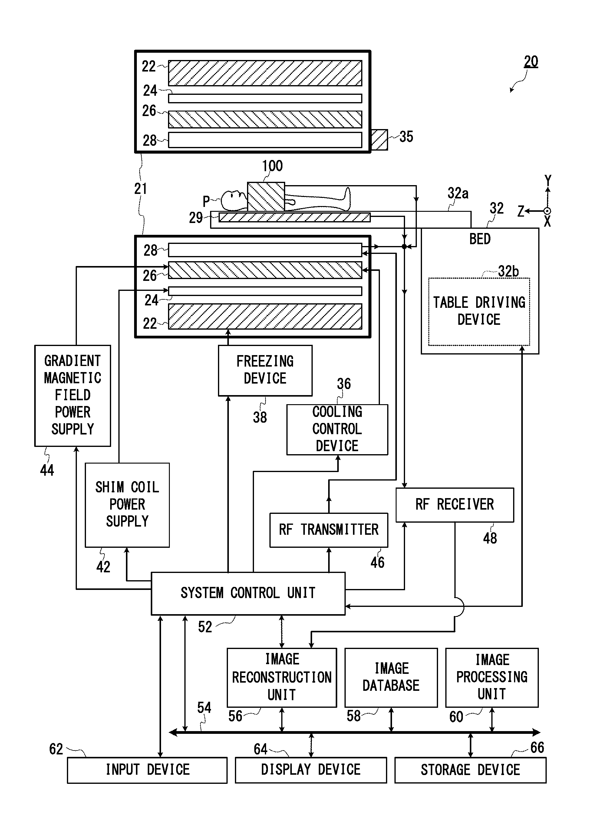
[0043]FIG. 2 is a functional block diagram mainly showing the structure of the imaging system of the MRI apparatus 20 of the first embodiment. As shown in FIG. 2, the MRI apparatus 20 includes a gantry 21, a bed 32 and a projector 35.
[0044]The bed 32 includes a table 32a and a table driving device 32b which moves the table 32a in a predetermined direction. The table 32a is movably supported by the bed 32. An object P is loaded on the table 32a.
[0045]The projector 35 is disposed on the portion of the opening of the gantry 21, and irradiates light for positioning towards the table 32a.
[0046]In addition, the MRI apparatus 20 includes a static magnetic field magnet 22, a shim coil 24, a gradient magnetic field coil 26, a transmission RF coil 28, a reception RF coil 29, a shim coil power supply 42, a gradient magnetic field power supply 44, an RF transmitter 46, an RF receiver 48 and a system control unit 52, as a data collecting system.
[0047]In addition, the MRI ap...
second embodiment
The Second Embodiment
[0277]FIG. 10 is a schematic circuit diagram of the electric power supply system of the MRI apparatus 20 of the second embodiment. Because the structure of the imaging system of the MRI apparatus 20 of the second embodiment to the fourth embodiment is the same as the first embodiment explained with FIG. 2, its explanation is omitted. The second embodiment is an embodiment in which a part of the power supply system of the first embodiment is changed in order to ensure that the battery unit BU is charged.
[0278]As the aforementioned equation (4), in order to charge the battery unit BU, it is desired to satisfy the electrifiable condition of (Vin2m / Tf2)1 / Tf1). By designing each component in accordance with the external power source 120 as input, the structure of the first embodiment sufficiently functions for practical use. On the other hand, the frequency and amplitude of the input of the external power source 120 differ per country, because it is, for example, a c...
third embodiment
The Third Embodiment
[0283]FIG. 11 is a schematic circuit diagram of the electric power supply system of the MRI apparatus 20 of the third embodiment. The third embodiment is an embodiment whose circuit structure is simplified by unifying the winding of the primary side of the second embodiment. Firstly, the circuit structure will be explained by focusing on the difference between the second embodiment and the present embodiment.
[0284]As shown in FIG. 11, the transformer TR′ in the third embodiment is the same as the transformer TR of the second embodiment shown in FIG. 10, except that the second primary winding Lf2 is omitted. The (first) primary winding Lf1 is magnetically coupled to each of the secondary windings Ls1 to Lsn, respectively.
[0285]In addition, in the third embodiment, the DC power supply 220, the current detector 136, the switch SW1 and the second switching circuit 148 of the second embodiment are omitted, and alternatively, “a direct-current power source 230 with out...
PUM
 Abstract
Description
Claims
Application Information