Optical filter and optical apparatus

a technology applied in the field of optical filters and optical apparatuses, can solve the problems of deteriorating image performance, many optical filters used in various applications, and light reflected by optical filters, so as to reduce reflection, improve image quality, and increase the flatness of spectral transmission characteristics

Active Publication Date: 2014-03-13
CANON DENSHI KK
View PDF3 Cites 13 Cited by
  • Summary
  • Abstract
  • Description
  • Claims
  • Application Information

AI Technical Summary

Benefits of technology

[0020]The present invention can provide an absorption-type optical filter with reduced reflection. The use of the optical filter in the imaging optical system can remarkably reduce problems such as ghost caused by reflection of the filter. The use of the filter with increased flatness of the spectral transmission characteristics can also remarkably improve, for example, color balance caused by spectral transmission. In addition, an imaging apparatus using such an optical filter particularly in a light diaphragm device can achieve a device for providing high-quality image.

Problems solved by technology

Many optical filters for use in various applications have problems caused by reflection of the filters themselves.
As a result, a problem caused by the light reflected by the optical filter occurs.
When an object is photographed in the field of high brightness or in good weather, such structured light diaphragm enters a so-called small aperture state, which is susceptible to influence such as a diaphragm hunting phenomenon and a light diffraction phenomenon, which may cause deterioration in image performance.
There is a case that these types may have a fatal drawback that the spectral transmittance has large wavelength dependence.
Even in the ND filter as such an optical filter, with respect to further high sensitivity, high resolution of the recent solid-state imaging element, there is an increasing possibility that a captured image has a problem such as ghost and flare caused by reflection of the filter itself as described above.
One of the big challenges for use in a camera under a strong light source has been performed to reduce the spectral reflectance in a visible wavelength region more than ever before.

Method used


Image

  • Optical filter and optical apparatus
  • Optical filter and optical apparatus
  • Optical filter and optical apparatus

Examples


first embodiment

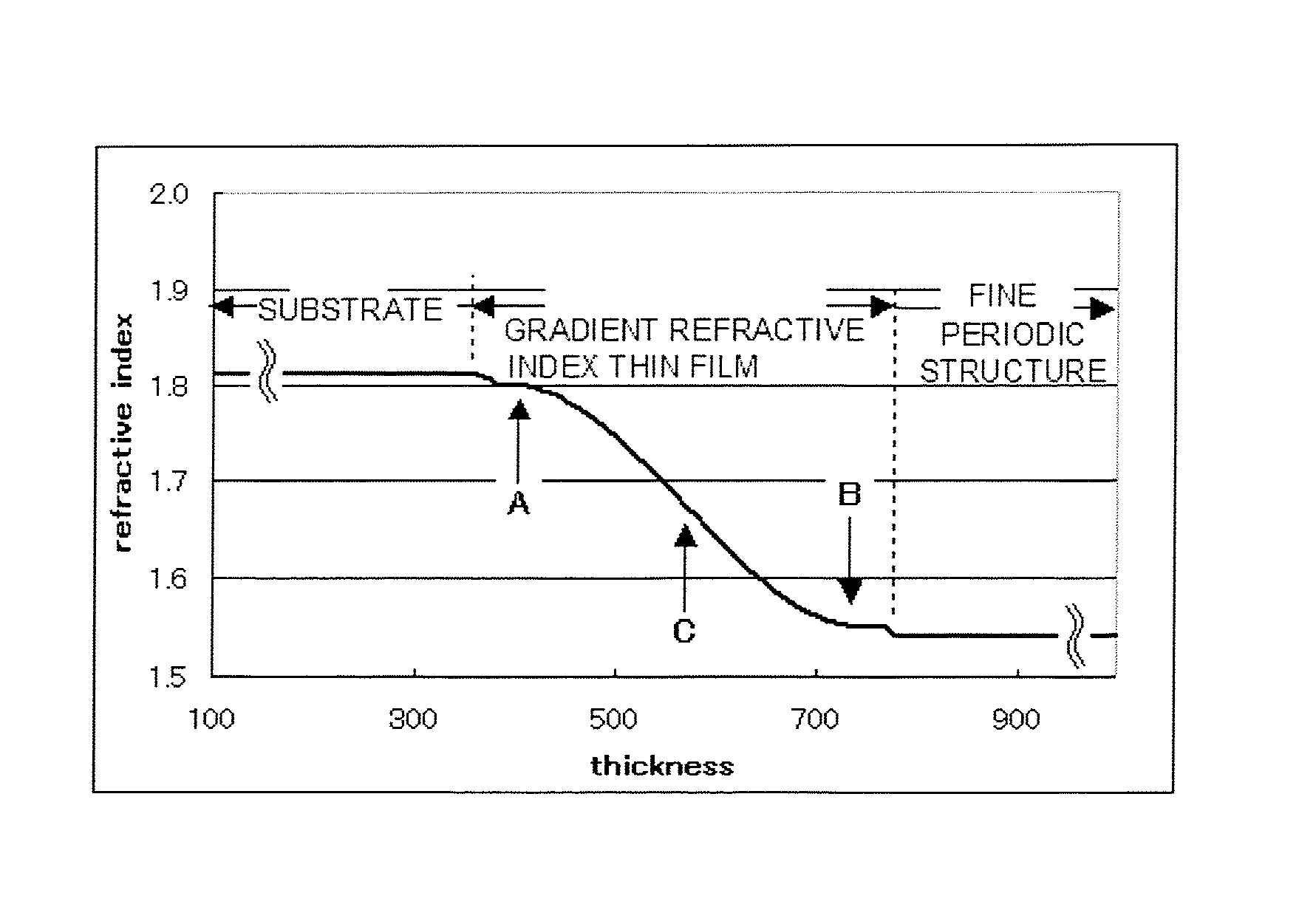
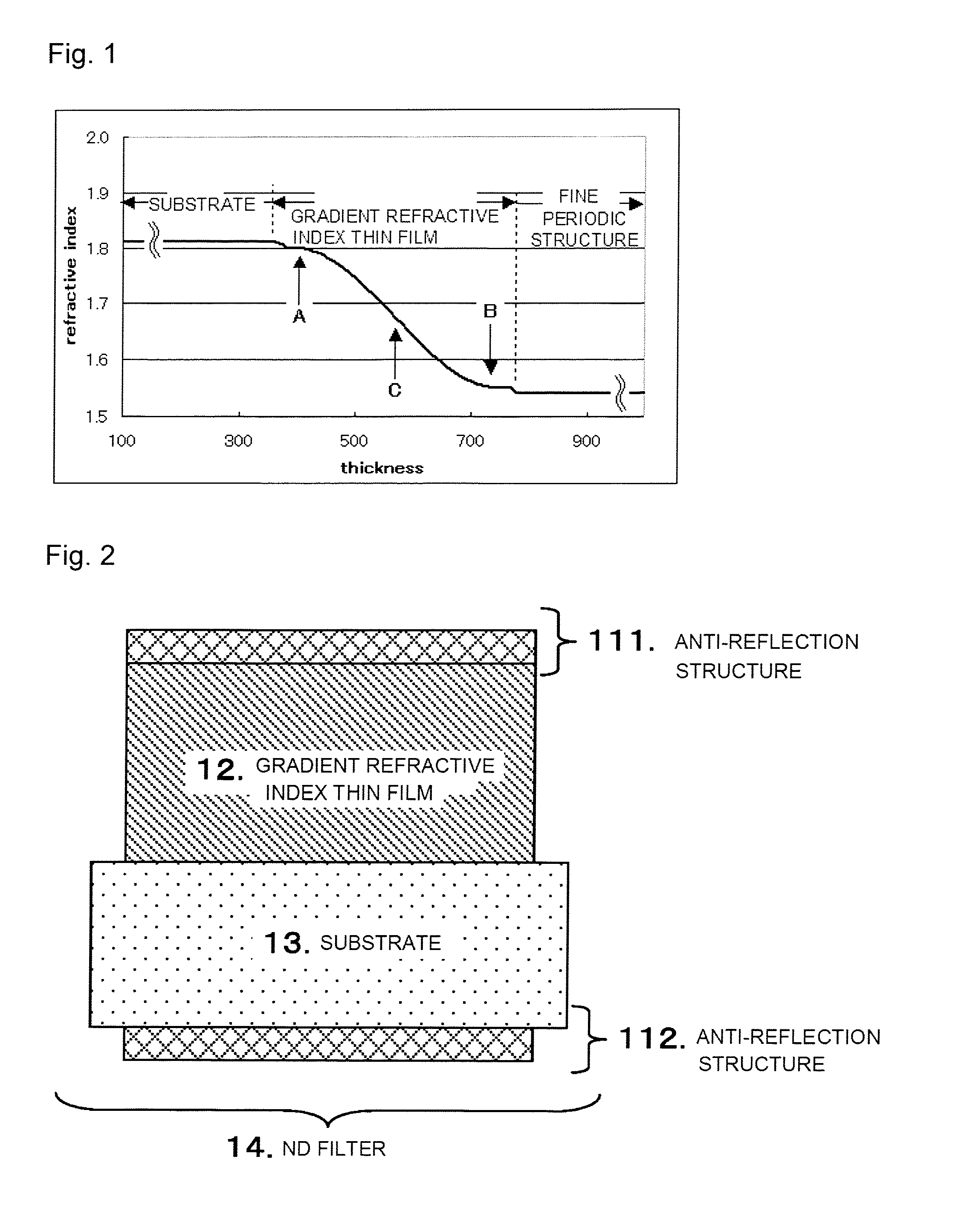
[0062]An absorption-type ND filter formed as illustrated in FIG. 2 will be described in detail as follows.

[0063]The refractive index for use in the embodiments and each example in the following description is identified as a refractive index of light with a wavelength of 540 nm from the materials of the substrate, the gradient refractive index thin film, and the anti-reflection structure.

[0064]As illustrated in FIG. 2, a gradient refractive index thin film 12 was arranged on one surface (upper surface) side of a substrate 13. When an anti-reflection structure 111 is arranged on the gradient refractive index thin film 12 and an anti-reflection structure 112 is arranged on a lower surface of the substrate 13, further anti-reflection effects can be obtained. In addition, at least an inner part of the gradient refractive index thin film 12 has absorption.

[0065]In a case of the structure as illustrated in FIG. 2, the reflection on the lower surface of the substrate will increase, and thu...

example 1

[0090]An absorption-type ND filter formed as illustrated in FIG. 2 will be described in detail as follows. In the present example, the gradient refractive index thin film 12, at least a part of which has absorption in the thin film, was arranged on one side of the substrate 13. The structure having no anti-reflection structure was made.

[0091]SFL-6 glass with a thickness of 1.0 mm and a refractive index of 1.81 was used to fabricate the substrate 13 for forming such an ND filter 14. In particular, for a single-sided film structure of the present example, a glass material was used to minimize the influence of water absorption of the substrate.

[0092]The gradient refractive index thin film 12 was fabricated in such a manner that the two kinds of materials were mixed by adjusting the film formation rate of the SiO2 and TiOx films by meta-mode sputtering. An adjustment was made such that the refractive index was continuously changed in the film thickness direction by continuously changing...

example 2

[0100]In the same manner as in Example 1, a substrate 13 was made from SFL-6 glass with a thickness of 1.0 mm and an ND filter including the substrate 13 and a gradient refractive index thin film 12 was fabricated. The gradient refractive index thin film 12 was adjusted and fabricated such that while adjusting the film formation rate of SiO2 and TiOx films by meta-mode sputtering so as to have a film thickness of 200 nm, the two kinds of materials were mixed and the composition thereof was continuously changed, thereby continuously changing the refractive index in the film thickness direction so as to obtain desired absorbing characteristics. In addition to this, by changing x of TiOx, the structure was made such that a region where the spectral transmittance in the visible wavelength region increases as approaching a long wavelength side and a region where the spectral transmittance in the visible wavelength region decreases as approaching the long wavelength side were provided in ...


PUM


Abstract

There is provided an optical filter of the type having absorption and with low reflection, which includes a light-transmitting substrate; and a light-absorbing gradient refractive index thin film provided on the substrate and whose refractive index changes so as to be close to the refractive index of the substrate toward the substrate side in a film thickness direction. There is also provided an optical apparatus using the optical filter.

Description

TECHNICAL FIELD[0001]The present invention relates to an optical filter having a light-absorbing gradient refractive index thin film provided on a light-transmitting substrate and an optical apparatus having an imaging optical system including the optical filter.BACKGROUND ART[0002]Many optical filters for use in various applications have problems caused by reflection of the filters themselves. For example, in some cases, an optical filter for use in an imaging optical system involves a phenomenon that part of light transmitted through the filter is reflected by another member and re-enters the optical filter from a light emitting surface of the optical filter. In such a case, if the optical filter has a reflectance in a wavelength region of the incident light, the light reflected by another member and re-entered is reflected again by the optical filter. As a result, a problem caused by the light reflected by the optical filter occurs. Therefore, further enhancement of the anti-refl...

Claims


Application Information

Patent Timeline
Patent Type & Authority Applications(United States)
IPC IPC(8): G02B5/22
CPCG02B5/22G02B1/115G02B3/0087G02B5/205G02B1/118
Inventor UCHIYAMA, MASAYUKIYANAGI, MICHIO
Owner CANON DENSHI KK
Why Eureka
Try Eureka