Variable displacement pump

a variable-discharge, pump technology, applied in the direction of pump control, positive-discharge liquid engine, rotary piston liquid engine, etc., can solve the problems of large electric energy loss, inability to obtain high pressure characteristic in the low engine speed region, etc., to reduce electric energy loss, high pressure characteristic, high pressure characteristic

Inactive Publication Date: 2014-03-13
HITACHI AUTOMOTIVE SYST LTD
View PDF6 Cites 28 Cited by
  • Summary
  • Abstract
  • Description
  • Claims
  • Application Information

AI Technical Summary

Benefits of technology

[0007]It is, therefore, an object of the present invention to provide a variable displacement pump devised to solve the above mentioned problems, and to decrease an electric energy loss for switching between a low pressure characteristic and a high pressure characteristic in a low engine speed region, and for obtaining the high pressure characteristic in a high engine speed region.

Problems solved by technology

Therefore, the loss of the electric energy may be large.
However, it is not possible to obtain the high pressure characteristic in the low engine speed region although the low pressure characteristic can be obtained in the low engine speed region.

Method used


Image

  • Variable displacement pump
  • Variable displacement pump
  • Variable displacement pump

Examples


first embodiment

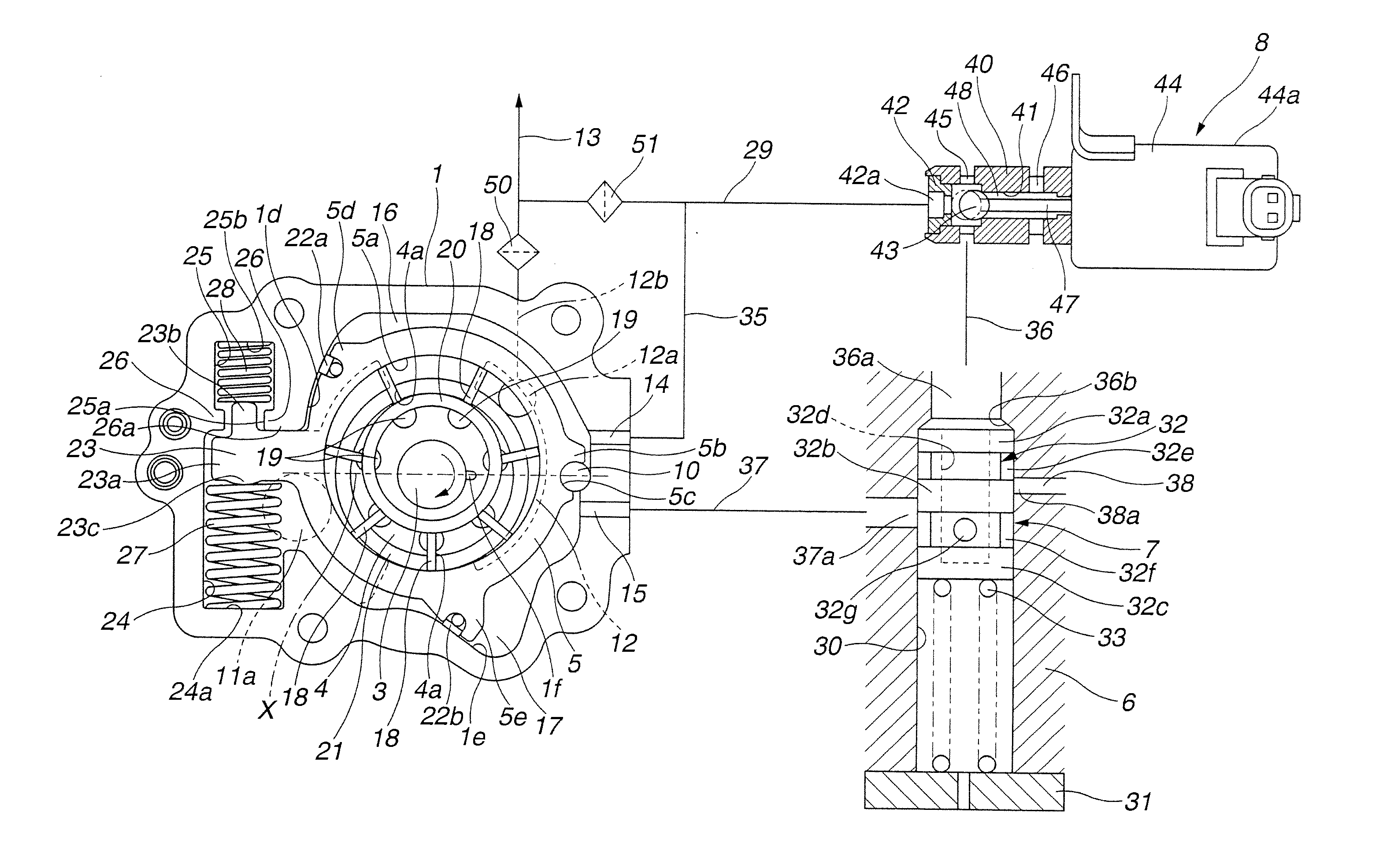
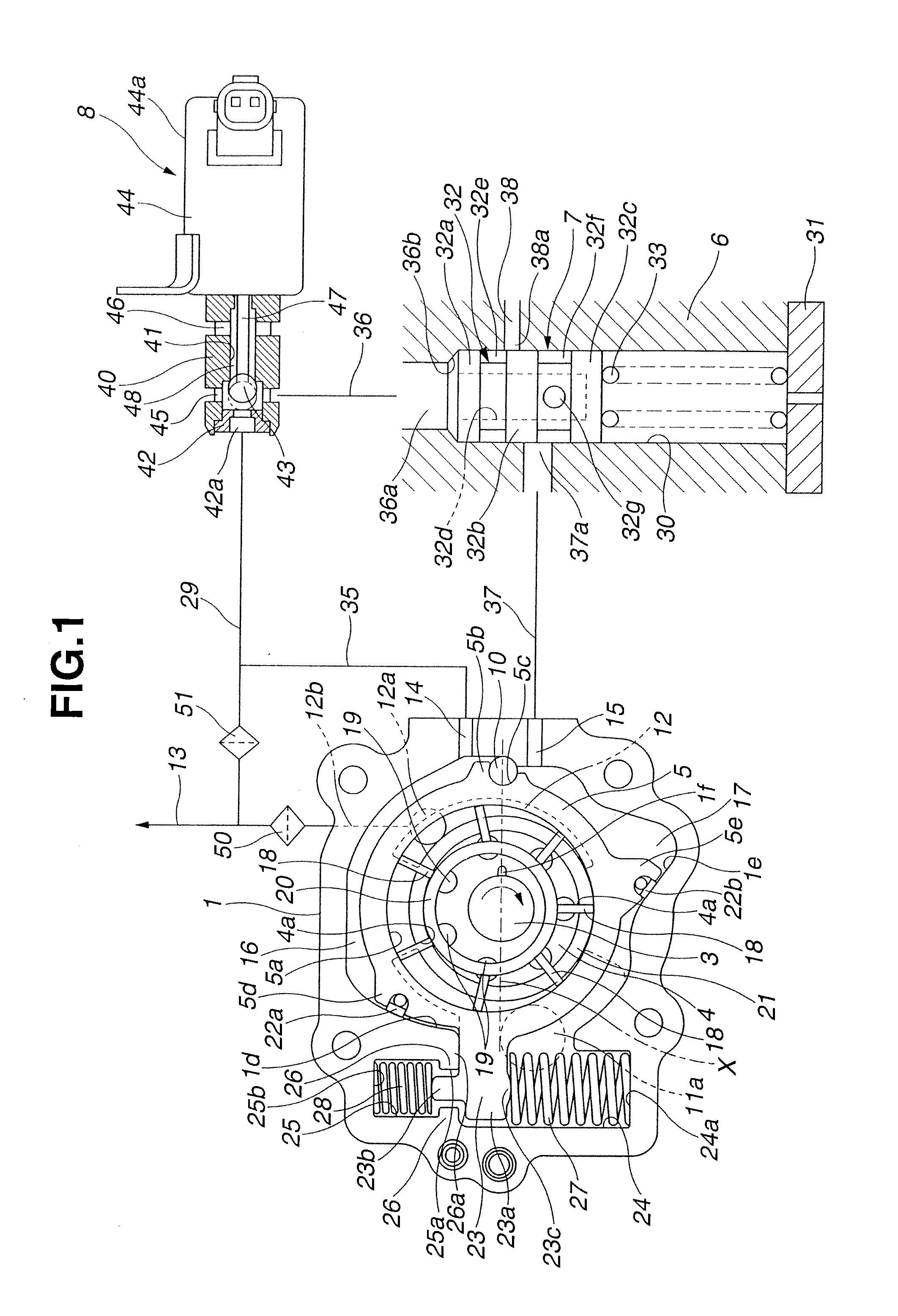
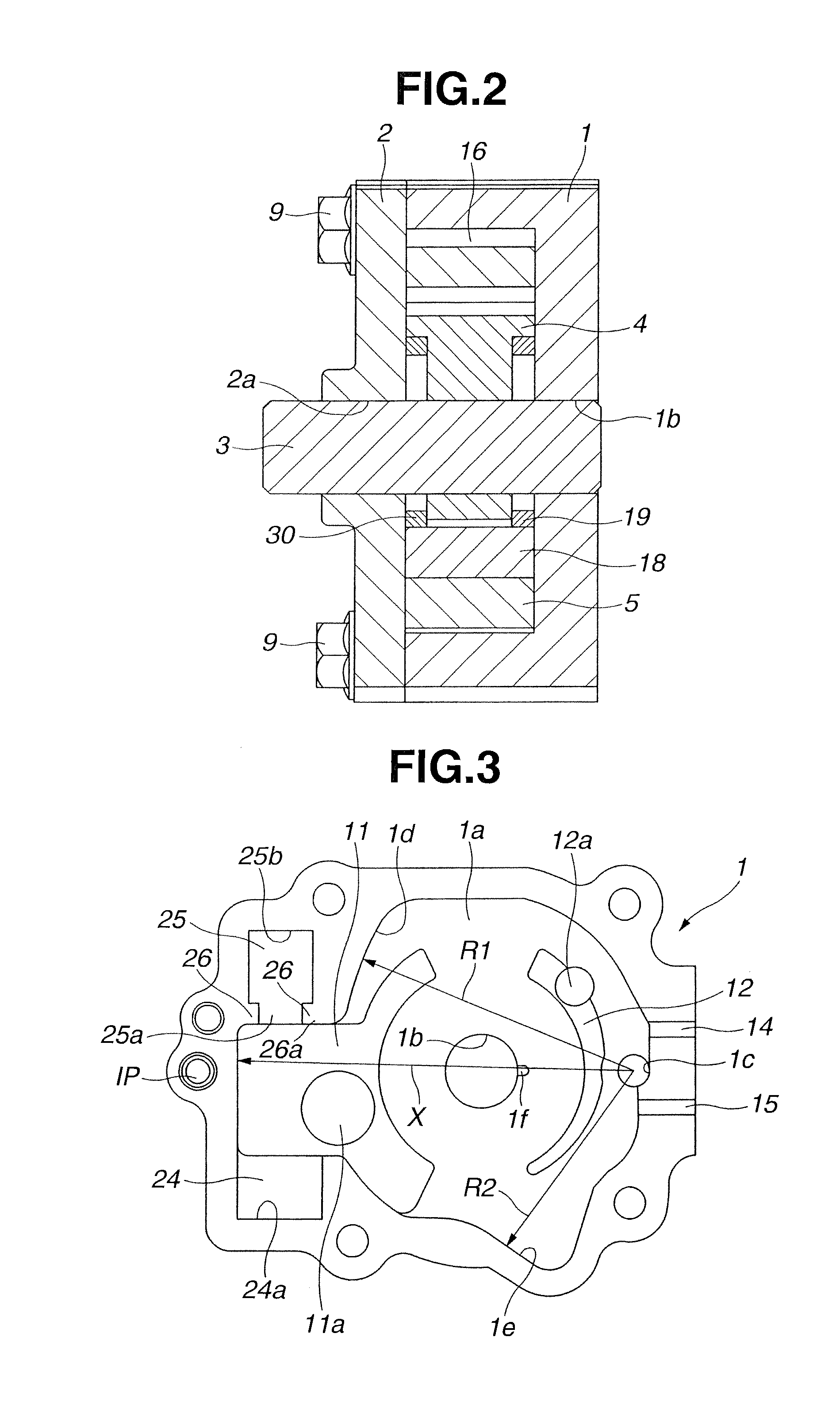
[0027]The variable displacement pump according to the first embodiment of the present invention includes a pump main body of a vane type. The variable displacement pump is provided to a front end portion of a cylinder block of an internal combustion engine. As shown in FIGS. 1 and 2, the variable displacement pump includes a pump housing 1 which includes one end opening that is closed by a pump cover 2, and the other bottomed end portion; a drive shaft 3 which penetrates through a substantially center portion of pump housing 1, and which is driven by the crank shaft of the engine; a rotor 4 which has a substantially H-shaped cross section, which is rotationally received within pump housing 1, and which includes a center portion connected with drive shaft 3; and a cam ring 5 which is a movable member that is swingably disposed radially outside rotor 4.

[0028]Moreover, the variable displacement pump includes a control housing 6 which is made from an aluminum alloy, and which is dispose...

second embodiment

[0131]FIG. 9 shows a variable displacement pump according to a second embodiment of the present invention. The structure of the pump main body and the structure of electromagnetic switching valve 8 in the variable displacement pump according to the second embodiment of the present invention are substantially identical to those of the variable displacement pump according to the first embodiment in most aspects as shown by the use of the same reference numerals. Accordingly, the repetitive illustrations are omitted. In the variable displacement pump according to the second embodiment of the present invention, a structure of pilot valve 7 and structures of the passages are different from those of the variable displacement pump according to the first embodiment. Therefore, hereinafter, these are illustrated.

[0132]That is, in pilot valve 7, sliding hole 30, and drain passage 38 having one end opening 38a formed in sliding hole 30 are formed within control housing 6. Siding hole 30 is for...

third embodiment

[0146]FIGS. 11-14 show a variable displacement pump according to a third embodiment of the present invention. In this third embodiment, first control hydraulic chamber 16 and a second control hydraulic chamber 57 do not sandwich pivot pin 10. First control hydraulic chamber 16 and second control hydraulic chamber 57 are disposed in parallel with each other on the upper side of pivot pin 10 in FIG. 11. Accordingly, when the hydraulic pressure is introduced into either of control hydraulic chambers 16 and 57, the eccentric amount of cam ring 5 is decreased, and the pump capacity is decreased.

[0147]Moreover, main oil gallery 13 is constantly connected through connection passage 35 to first control hydraulic chamber 16, and connected through first branch passage 29 to solenoid opening port 42a of electromagnetic switching valve 8. Furthermore, main oil gallery 13 is connected through a second branch passage 59 to a downstream side opening end 59a of pilot valve 7.

[0148]Arm 23 of cam rin...


PUM


Abstract

A variable displacement pump includes: an urging mechanism which includes two spring members; an electromagnetic switching valve which is arranged to connect the second control chamber and the discharge portion in an energized state, and to connect the second control chamber and the low pressure chamber in a deenergized state; and a control valve which is actuated by the pressure of the discharge portion, and which is arranged to decrease the pressure within the second control chamber when the pressure of the discharge portion becomes equal to or greater than a predetermined pressure.

Description

BACKGROUND OF THE INVENTION[0001]This invention relates to a variable displacement pump arranged to supply oil to sliding portions of an internal combustion engine for a vehicle and so on.[0002]In recent years, an oil discharged from an oil pump is used for a driving source of a variable valve actuating device, an oil jet arranged to cool a piston, and a lubrication of a bearing of a crank shaft. The driving source of the variable valve actuating device, the oil jet, and the lubrication of the bearing of the cranks shaft have different desired discharge pressures. Accordingly, there are demands that a low pressure characteristic and a high pressure characteristic are switched in a low engine speed region, and that the high pressure characteristic is obtained in the high engine speed region. Japanese Patent Application Publication No. 2008-524500 (corresponding to U.S. Patent Application Publication No. 2009 / 0022612, U.S. Patent Application Publication No. 2010 / 0329912, and U.S. Pate...

Claims


Application Information

Patent Timeline
Patent Type & Authority Applications(United States)
IPC IPC(8): F04B17/00
CPCF04B17/003F04C2/344F04C14/226F04B17/05F04B49/002F04C2/3442F04C14/223
Inventor WATANABE, YASUSHINAGANUMA, ATSUSHI
Owner HITACHI AUTOMOTIVE SYST LTD
Why Eureka
Try Eureka