Method and System for Monitoring and Reporting Equipment Operating Conditions and Diagnostic Information

a technology of equipment operating conditions and diagnostic information, applied in the direction of instrumentation, programme control, total factory control, etc., can solve the problems of manual inspection incurring four significant problems, manual inspection generally involves risks associated with the environment and operating conditions of equipment, and manual inspection can involve a significant waste of personnel resources

Inactive Publication Date: 2014-03-13
CBM ENTERPRISE SOLUTIONS
View PDF10 Cites 21 Cited by
  • Summary
  • Abstract
  • Description
  • Claims
  • Application Information

AI Technical Summary

Benefits of technology

[0009]A primary advantage of the invention is to provide a system for managing and analyzing large quantities of data that is scalable.
[0010]Another advantage of the invention is to provide a system for monitoring systems and machinery on to near real time basis.
[0011]Another advantage of the invention is to provide a user configurable data retrieval system for monitoring and assessing system operating conditions.
[0012]Another advantage of the invention is to allow for distributed ...

Problems solved by technology

Manual inspection incurs four significant problems.
First, manual inspection generally involves risks associated with the environment and operating conditions of the equipment.
Second, manual inspection can involve a significant waste of resources in connection with personnel travelling between various pieces of equipment in various locations, as well as time spent collecting and analyzing data.
Third, manual inspection is generally not executed by personnel who are experts in the various fields of concern, e.g., vibration, thermodynamics, and other operating conditions.
Finally, data collected is inconsistent due to variances related to the method of inspection, e.g., sensor placement and inspections being performed at irregular intervals.
Beyond the concerns ...

Method used


Image

  • Method and System for Monitoring and Reporting Equipment Operating Conditions and Diagnostic Information
  • Method and System for Monitoring and Reporting Equipment Operating Conditions and Diagnostic Information
  • Method and System for Monitoring and Reporting Equipment Operating Conditions and Diagnostic Information

Examples


Embodiment Construction

[0027]Detailed descriptions of preferred embodiments of the invention are provided herein. It is to be understood, however, that the present invention may be embodied in various forms. Therefore, specific details disclosed herein are not to be interpreted as limiting, but rather as a basis for the claims and as a representative basis for teaching one skilled in the art how to employ the present invention in virtually any appropriately detailed system, structure or manner.

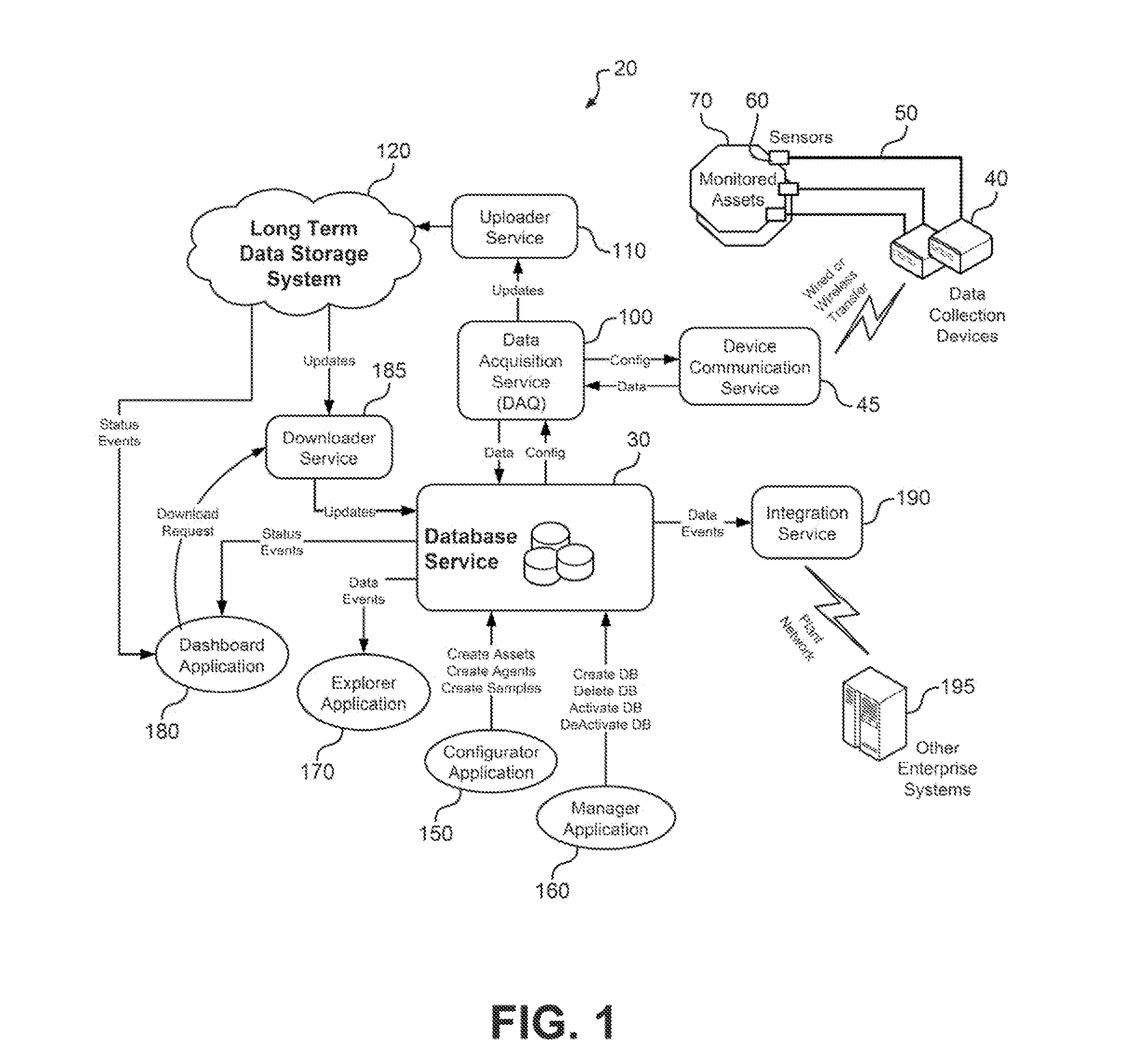
[0028]With initial reference to FIG. 1, there is shown an overall system 20 for monitoring and reporting equipment operating conditions and diagnostic information. As depicted, a database service including a first, preferably local database or databases 30 provides an area to store information. Data is initially collected by data collection devices 40 which are linked by communication wires to individual sensors 60 attached to a monitored asset 70 which may be as group of machines or various pieces of equipment or i...


PUM


Abstract

A method and system (20) is provided for condition based monitoring reliability maintenance capabilities for an asset (70), such as one or more machines, by establishing a network including of a sensor (60) or a plurality of sensors installed, temporarily or in generally fixed locations, on asset (70), wherein sensor (60) provides time sequenced operational information in the form of data based on vibrations, temperature, electrical signals, or other operating conditions. Sensors (60) are connected to a local controller (40) which transmits the data via a local or wide area network (45), either through wired or wireless communication paths, in data packets, each containing divided portions of the operational information. The data packets are mapped and stored into multiple, dedicated databases for ease of retrieving and analyzing the data. Preferably, a cloud-based storage arrangement (120) is employed to storing the mapped data.

Description

CROSS REFERENCE TO RELATED APPLICATIONS[0001]This application claims the benefit of U.S. Provisional Patent Application Ser. No. 61 / 533,188 filed on 10 Sep. 2011, entitled “Method and Apparatus For Monitoring and Reporting Equipment Operating Conditions and Diagnostic Information,” which is incorporated herein by reference.BACKGROUND OF THE INVENTION[0002]The present invention pertains to the field of predictive and reliability centered system maintenance and, more specifically, to a method and apparatus for monitoring and reporting equipment operating conditions and diagnostic information. More particularly, the present invention relates to a condition based monitoring network and method which employs local and wide area networks to provide operating condition data to local and remote users with the necessary software to read and analyze data, as well as providing a user interface.[0003]Operators of machinery must balance the often competing concerns of maximizing operational time ...

Claims


Application Information

Patent Timeline
IPC IPC(8): G06F19/00
CPCG06F19/00G06F11/3013G06F11/3058G05B19/4183G05B2219/31282G05B2219/31319G05B2219/32235G06F17/40G05B23/0283Y02P90/02Y02P90/80G16Z99/00G01D3/08G07C3/00G01D21/00G06F11/3495G07C3/14
Inventor BOYD, CINDY L.RAJAB, MAJDIBORODAEV, ANATOLYFEDISHOV, VLADIMIR
Owner CBM ENTERPRISE SOLUTIONS
Why Eureka
Try Eureka