
Dynamic Faceplates For Multiple Objects

a technology of dynamic faceplates and objects, applied in the field of process control systems, can solve the problems of user confusion about the faceplates on the display device screen, and achieve the effect of reducing the hiding of important process graphics or even eliminating them

Active Publication Date: 2014-03-13
ABB (SCHWEIZ) AG
View PDF11 Cites 6 Cited by
  • Summary
  • Abstract
  • Description
  • Claims
  • Application Information

AI Technical Summary

Benefits of technology

The present invention provides a method and user interface for displaying multiple faceplates simultaneously. This allows for efficient working with several faceplates and reduces cluttering of the display. The user interface allows for easy identification of which faceplate is being displayed and which graphical elements are important. This improves user experience and decision-making. Additionally, the invention provides a way to hide important graphical elements and display them in a separate region of the user interface.

Problems solved by technology

In particular when working with several faceplates simultaneously, the user may become unsure where on the screen of the display device the faceplates will appear.

Method used


Image

  • Dynamic Faceplates For Multiple Objects
  • Dynamic Faceplates For Multiple Objects
  • Dynamic Faceplates For Multiple Objects

Examples


Embodiment Construction

[0071]The present invention will now be described more fully hereinafter with reference to the accompanying drawings, in which exemplifying embodiments of the present invention are shown. The present invention may, however, be embodied in many different forms and should not be construed as limited to the embodiments set forth herein; rather, these embodiments are provided by way of example so that this disclosure will convey the scope of the present invention to those skilled in the art. Furthermore, like numbers refer to like or similar elements or components throughout. The steps of any method disclosed herein do not have to be performed in the exact order disclosed, unless explicitly stated.

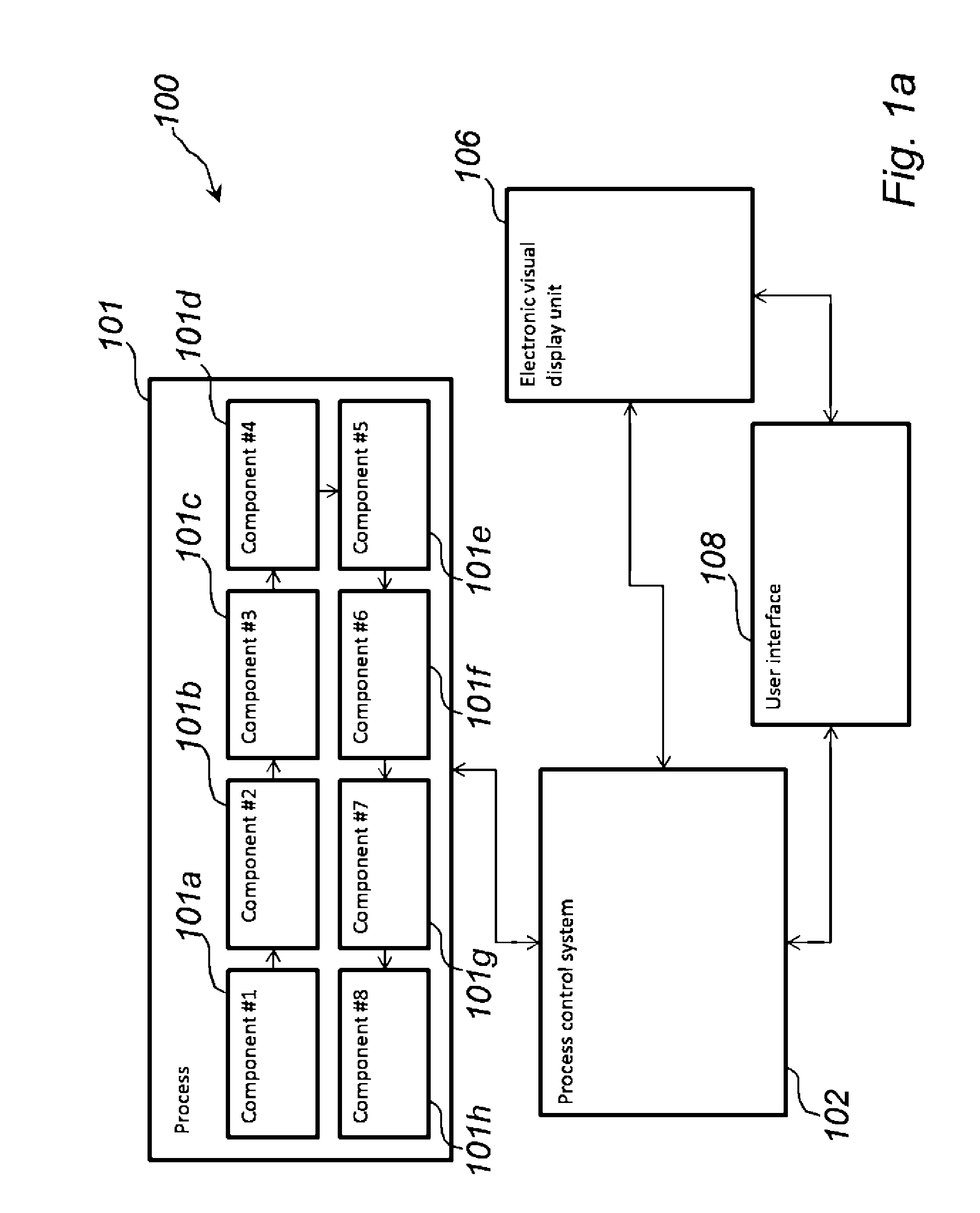
[0072]Referring now to FIG. 1a, there is shown a schematic block diagram of a system 100 in accordance with an exemplifying embodiment of the present invention.

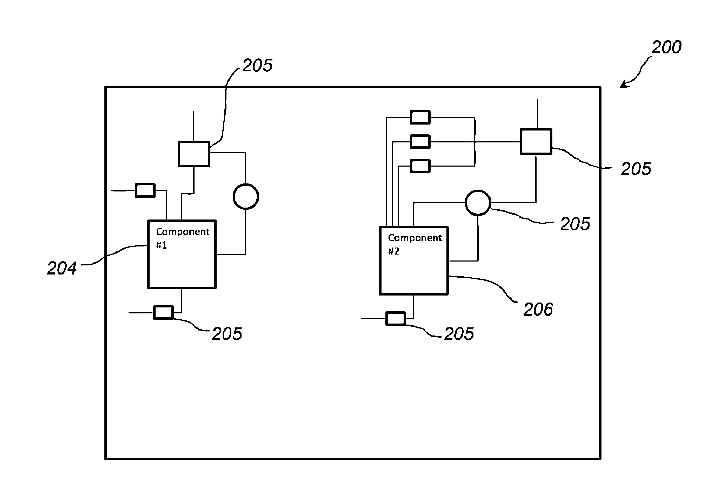
[0073]The system 100 comprises a process 101 comprising several components, sub-processes, or steps 101a-101h. Each component 101a-101...


PUM


Abstract

A method in a UI of a process control system is disclosed. The UI is configured to be displayed on an electronic visual display unit connectable to the process control system. The UI is adapted to visually indicate a plurality of components included in at least a part of a process controlled by the process control system. At least one sub-UI, such as a faceplate, is generated, each sub-UI corresponding to a respective component of the plurality of components. The at least one sub-UI is displayed on the display unit. Each of the at least one sub-UI is adapted such that a number of operation information and / or control elements visually indicated in each sub-UI when the at least one sub-UI is displayed on the display unit depends on the number of sub-UIs that are displayed on the display unit at the same time. Furthermore, such a UI is disclosed.

Description

FIELD OF THE INVENTION[0001]The present invention generally relates to process control systems for controlling a process. Specifically, the present invention relates to a method in a user interface (UI) of a process control system and a UI of a process control system.BACKGROUND OF THE INVENTION[0002]Processing facilities are often managed using process control systems. In process control systems for controlling and / or monitoring an industrial process, the operator typically controls / monitors the entire process or different parts of the process by means of one or more user interfaces (UIs), for example constituted by one or more graphic windows displayed on a display screen, where each graphic window may display process graphics. Such UIs may enable the operator to monitor the status of the different components of the process and / or control the operation of individual components of the process by means of user input provided to the UI. Such operations typically comprise operation of ...

Claims


Application Information

Patent Timeline
IPC IPC(8): G06F3/0482
CPCG06F3/0482G05B19/418G05B2219/31472Y02P90/02G06F9/451
Inventor TIMSJO, SUSANNEOLAUSSON, MARTIN
Owner ABB (SCHWEIZ) AG
Learn More