Ocean Wave Energy Converter (OWEC) with Counter-Rotating Flywheels

a technology of counter-rotating flywheels and ocean waves, applied in the direction of electric generator control, machines/engines, therapy, etc., can solve the problems of wave speed, energy loss, and form a backwash, so as to prevent damage to the owec, increase the production of electrical energy, and increase the power

Inactive Publication Date: 2014-03-20
GILL LONDONO ALFREDO
View PDF5 Cites 17 Cited by
  • Summary
  • Abstract
  • Description
  • Claims
  • Application Information

AI Technical Summary

Benefits of technology

[0019]The float of the OWEC comprises buoyancy chambers, such as one each on opposing ends of the float. The buoyancy chambers support the float's weight in order to keep only about 5% of the OWEC's float above the sea surface. All prior art systems are built with approximately 50-80% of the OWEC above the sea surface due to the limitations of the way they are constructed. The advantage of the much greater degree of submersion of the current invention over prior art systems is to prevent damage to the OWEC from surface waves, especially during storm conditions.
[0020]The float of the present invention further comprises reflectors on the underside of the float for receiving the upward column of water being generated by the spar reflectors, and to channel the flow of water upward against the float's bottom surface. This flow thus increases the power with which the float is pushed upward, as compared to the prior art floats of merely riding a wave upward / downward. And the increase in power correlates with an increase in electrical energy production.

Problems solved by technology

The friction against the increasingly shallow sea floor approaching the coast causes the waves to slow and ultimately form a backwash.
Energy is thus rapidly lost.
These systems have been shown, though, to damage the float during adverse weather conditions, such as excessively high tide, extraordinarily high waves, and typhoons.
Additionally, conversion of a float's movement within OWEC's, such as the listed prior art, into electrical energy is difficult because of the slow oscillations of the float riding on the waves.

Method used


Image

  • Ocean Wave Energy Converter (OWEC) with Counter-Rotating Flywheels
  • Ocean Wave Energy Converter (OWEC) with Counter-Rotating Flywheels
  • Ocean Wave Energy Converter (OWEC) with Counter-Rotating Flywheels

Examples


Embodiment Construction

Adverse Weather

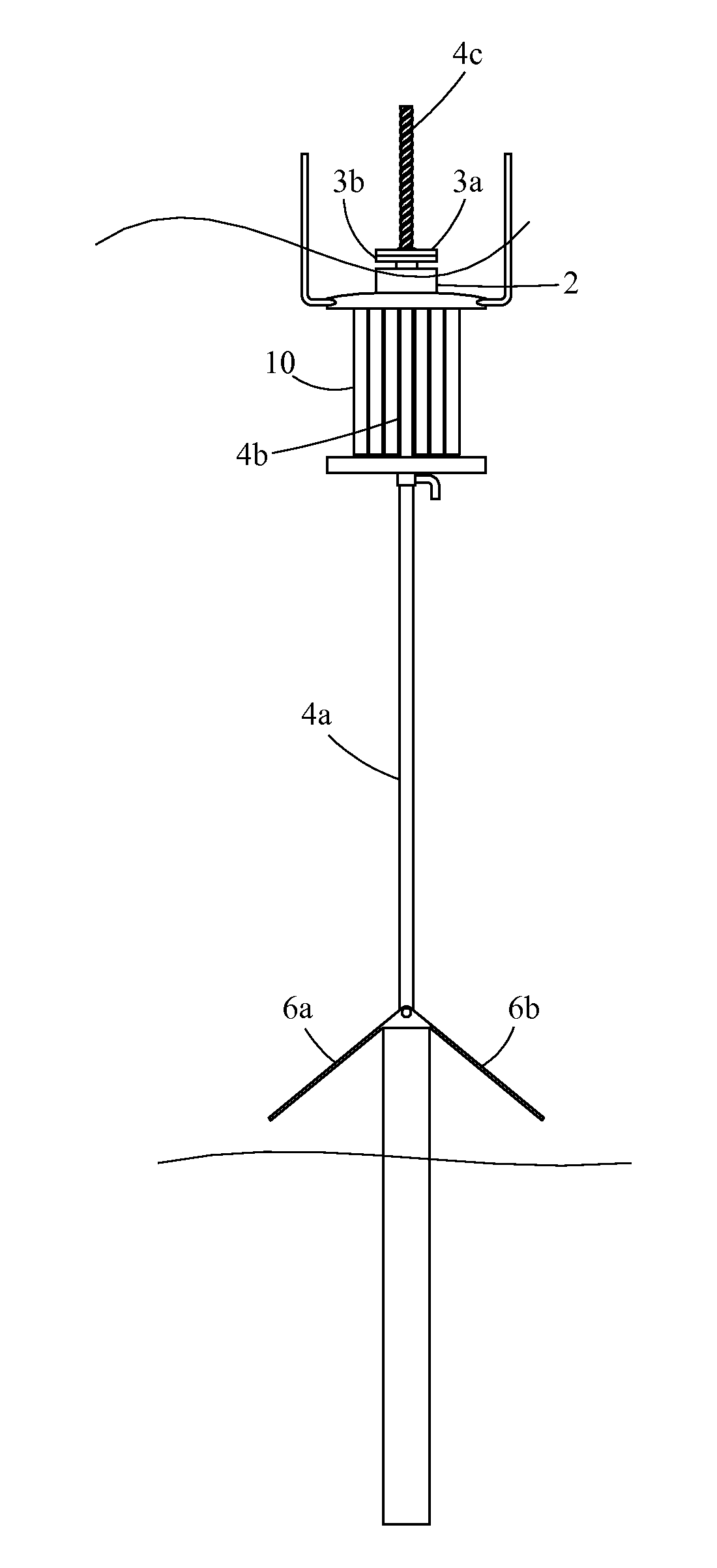
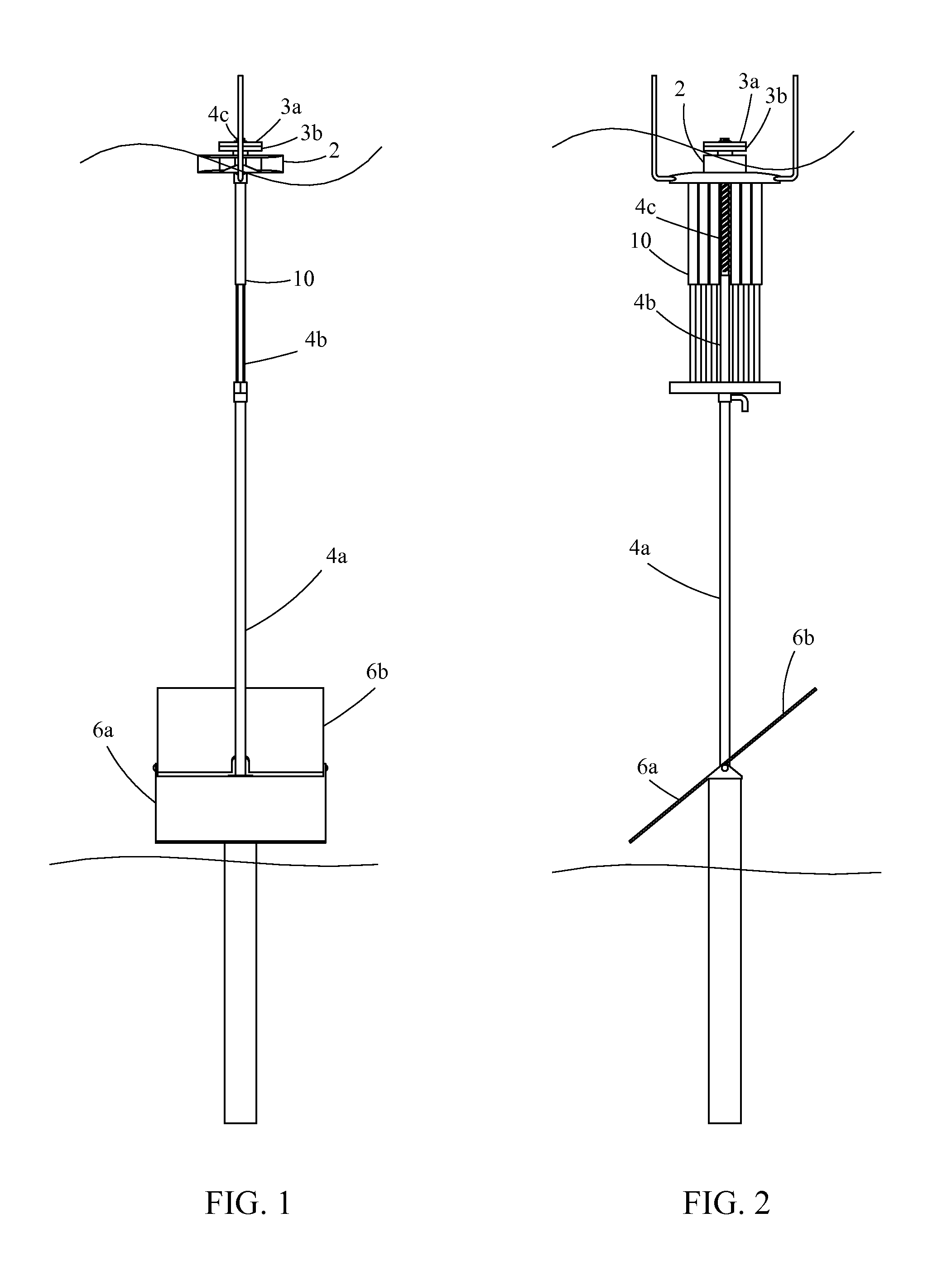
[0086]The OWEC of the present invention has the advantage over prior art OWEC's of being able to protect the OWEC during adverse weather conditions. For example, FIGS. 1-4 illustrate the ability of the PTO's computer system to reposition the OWEC's float 2 and the spar reflectors 6a,b depending on the weather conditions. FIGS. 1 and 2 are the OWEC's front and side views, respectively, during normal weather conditions. The float 2 is extended to the spar's top section 4c, while the spar reflectors 6a,b are in the fully extended position and angled about 30-40 degrees from the horizontal wave flow to optimize the amount of water re-directed upward while minimizing the amount of turbulence produced.

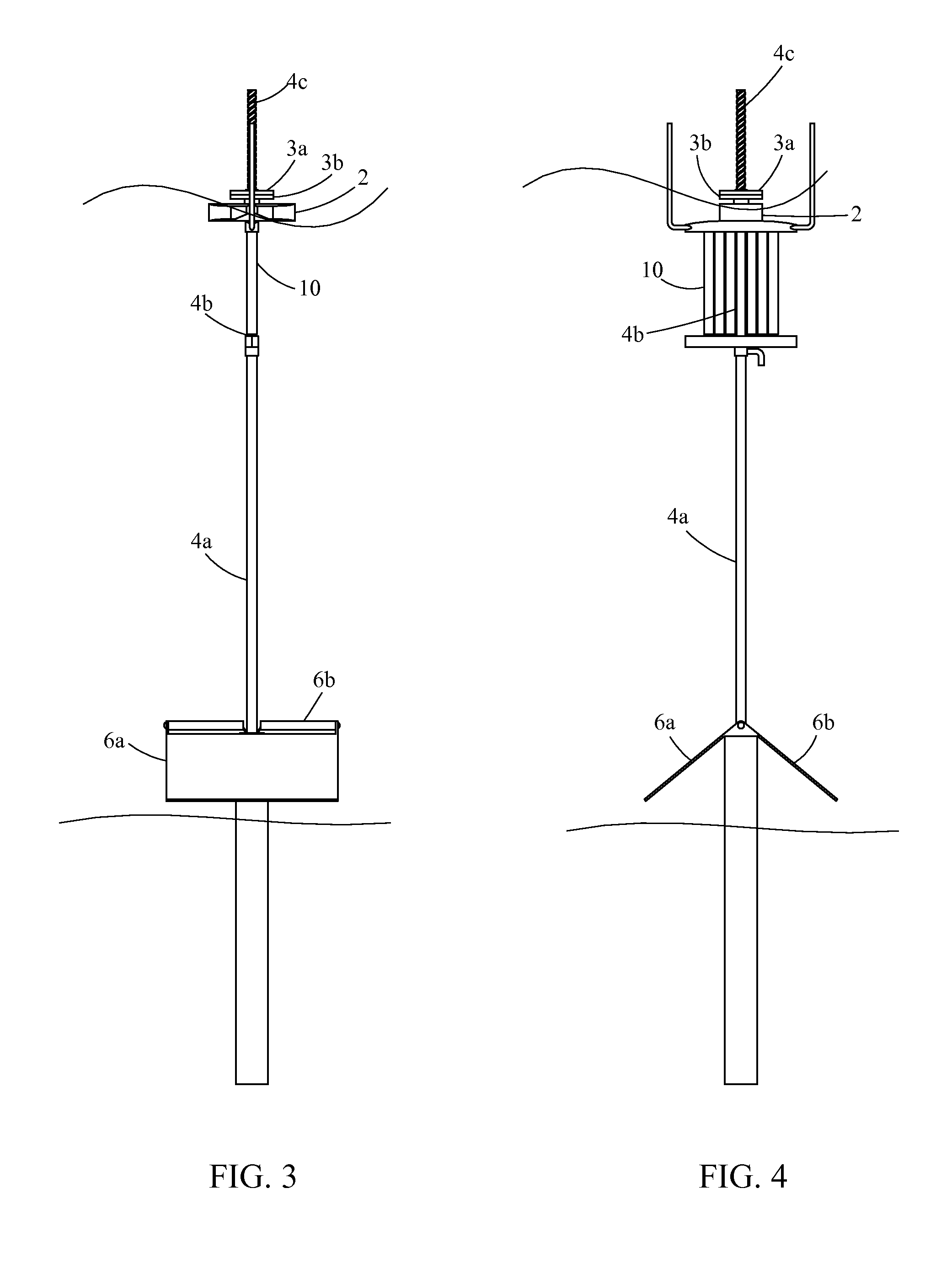
[0087]Likewise, FIGS. 3 and 4 illustrate the OWEC during adverse weather conditions with the float 2 lowered on the spar section 4c, and the spar reflector 6b rotated to a position that is approximately 90 degrees from its upward position shown in FIGS. 1 and 2. In this positi...


PUM


Abstract

An OWEC designed to convert the energy of an oscillating water column within a wave into electricity for use during peak hours and into compressed air for use during off peak hours, and to withstand adverse weather conditions. Located off-shore, and submerged about 95%, the OWEC comprises: a vertically adjustable spar comprising a vertical shaft connected to a foundation in the sea floor, and extending above sea level; a float comprising parabolic reflectors on the underside to channel wave flow upward, and two buoyancy chambers to support the float's weight; adjustable parabolic spar reflectors attached near the spar's bottom to re-direct horizontal wave flow vertically to maximize the float's produced power; a cylinder system to generate compressed air that is stored in an onsite tank; and, a power takeoff (PTO) device sitting atop the float and comprising two counter-rotating flywheels to convert the float's power into electrical energy.

Description

CROSS-REFERENCE TO RELATED APPLICATIONS[0001]This application is a continuation-in-part of U.S. patent application Ser. No. 13 / 616,416 filed Sep. 14, 2012, by Gill Londono, and entitled “OCEAN WAVE ENERGY CONVERTER (OWEC) WITH PARABOLIC REFLECTORS”, the entire disclosure of which is hereby incorporated by reference.FIELD OF THE INVENTION[0002]The present invention relates to renewable energy, in particular an ocean wave energy converter to convert vertical and horizontal oscillating wave flow into compressed air power (e.g. a water powered gas compressor) and electricity.BACKGROUND OF THE INVENTION[0003]Ocean Wave Energy Converters (OWEC's) are devices designed to absorb the energy of the vertical, up / down oscillating motion of a wave's water column and convert it into electrical, pressurized air and / or fluid energy. Ocean waves can travel thousands of miles without losing energy. Ideally, OWEC's are located a significant distance offshore in approximately 50 meters or more of ocean...

Claims


Application Information

Patent Timeline
Patent Type & Authority Applications(United States)
IPC IPC(8): F03B13/18
CPCF03B13/1855A61N5/0601A61N5/062A61N2005/063F03B13/142F05B2240/12F05B2260/40F05B2260/421Y02E10/30
Inventor GILL LONDONO, ALFREDO
Owner GILL LONDONO ALFREDO
Why Eureka
Try Eureka