Bandgap Reference Circuit and Self-Referenced Regulator

a reference circuit and self-reference technology, applied in the direction of electric variable regulation, process and machine control, instruments, etc., can solve the problems of increasing circuit power consumption, circuit complexity, layout area, circuit power consumption, etc., and achieves low system voltage and small layout area

Active Publication Date: 2014-03-20
NOVATEK MICROELECTRONICS CORP
View PDF7 Cites 36 Cited by
  • Summary
  • Abstract
  • Description
  • Claims
  • Application Information

AI Technical Summary

Problems solved by technology

Therefore, although the bandgap reference circuit 10 may meet the requirements for a portion of low voltage bandgap reference circuits, the bandgap reference circuit 10 still can not satisfy applications with the system voltage of 1V.
Besides, although the operational transconductance amplifier 100 can lock the input voltage VIN+ and VIN− under the low system voltage condition, the operational transconductance amplifier 100 increases circuit complexity, layout area, and circuit power consumption in comparison with a general bandgap reference circuit which does not require operating under low voltage.
In addition to increasing additional layout area and circuit power consumption, the temperature coefficient of the zero temperature coefficient current IREF and the temperature coefficient of the zero temperature coefficient voltage VREF may also be affected when the resistors RL′ and RL are mismatched (i.e. the resistance ratio L between the resistors RL′ and RL does not satisfy the condition in equation (3)), such that the zero temperature coefficient current IREF and the zero temperature coefficient voltage VREF do not completely have a zero temperature coefficient.
As can be seen from the above, since the conventional bandgap reference circuit for low system voltage utilizes the conventional operational transconductance amplifier to lock the input voltage of the input terminals to generate the positive temperature coefficient current and needs the additional resistors to balance the circuit for generating the negative temperature coefficient current, the circuit structure is complex.

Method used


Image

  • Bandgap Reference Circuit and Self-Referenced Regulator
  • Bandgap Reference Circuit and Self-Referenced Regulator
  • Bandgap Reference Circuit and Self-Referenced Regulator

Examples


Embodiment Construction

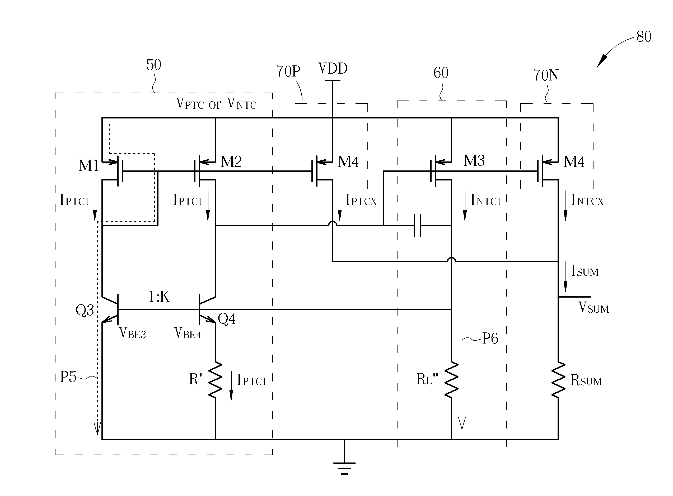
[0035]Please refer to FIG. 4, which illustrates a schematic diagram of a bandgap reference circuit 40 according to an embodiment of the present invention. As shown in FIG. 4, the bandgap reference circuit 40 includes a dual-output self-referenced regulator 400 and a reference generation circuit 402. In short, the dual-output self-referenced regulator 400 includes a self-biased operational transconductance amplifier 404 and a feedback voltage amplifier 406. The self-biased operational transconductance amplifier 404 utilizes an area difference between bipolar junction transistors of an input pair to generate a positive temperature coefficient current IPTC1 to bias the input pair, and generates a positive temperature coefficient control voltage VPTC and a negative temperature coefficient control voltage VNTC. The feedback voltage amplifier 406 amplifies the negative temperature coefficient control voltage VNTC, and outputs a reference voltage VF to the input pair of the self-biased ope...


PUM


Abstract

The present invention discloses a bandgap reference circuit. The bandgap reference circuit includes an operational transconductance amplifier, and a reference generation circuit. The operational transconductance amplifier includes a self-biased operational transconductance amplifier, for utilizing an area difference between bipolar junction transistors of an input pair to generate a first positive temperature coefficient current to bias the input pair, and generating a positive temperature coefficient control voltage and a negative temperature coefficient control voltage; and a feedback voltage amplifier, for amplifying the negative temperature coefficient control voltage, and outputting a reference voltage to the input pair for feedback, to generate a first negative temperature coefficient current. The reference generation circuit generates a summation voltage or a summation current according to the positive temperature coefficient control voltage and the negative temperature coefficient control voltage.

Description

BACKGROUND OF THE INVENTION[0001]1. Field of the Invention[0002]The present invention relates to a bandgap reference circuit and a related dual-output self-referenced regulator, and more particularly, to a bandgap reference circuit and a related dual-output self-referenced regulator having low system voltage and small layout area.[0003]2. Description of the Prior Art[0004]With the advancement of digital product, a large number of applications for handheld devices appear. Such applications utilize lower system voltage for reducing power consumption. If the circuits of such applications require a reference voltage which does not change with temperature, the circuits needs to utilize a bandgap reference circuit which can be applied in low system voltage operations and can simultaneously provide the low reference voltage.[0005]For example, please refer to FIG. 1, which illustrates a schematic diagram of a conventional bandgap reference circuit 10. As shown in FIG. 1, in the bandgap refe...

Claims


Application Information

Patent Timeline
Patent Type & Authority Applications(United States)
IPC IPC(8): G05F3/02
CPCG05F3/02G05F3/30
Inventor HU, MIN-HUNGHUANG, CHIU-HUANGWU, CHEN-TSUNG
Owner NOVATEK MICROELECTRONICS CORP
Why Eureka
Try Eureka