Band-pass filter

Inactive Publication Date: 2014-03-20
TATUNG COMPANY
View PDF4 Cites 8 Cited by
  • Summary
  • Abstract
  • Description
  • Claims
  • Application Information

AI Technical Summary

Benefits of technology

The invention provides a band-pass filter that can maintain its filtering function without increasing its size and effectively prevent the issue of high frequency harmonic noise. This is achieved by forming coupling structures between different conductor layers of the double-sided circuit board, which maintains the microstrip structure and the band-pass filtering function.

Problems solved by technology

Recently, as mobile communication techniques have advanced rapidly and the microwave communication industry has also grown in relative terms, the importance of high frequency circuit design cannot be ignored.
However, a common problem with the two aforementioned types of band-pass filters is the harmonic noise issue. FIG. 3 is a frequency response diagram of a hairpin band-pass filter obtained from an electromagnetic simulation.
Accordingly, the design and manufacturing costs are increased drastically.

Method used


Image

  • Band-pass filter
  • Band-pass filter
  • Band-pass filter

Examples


Embodiment Construction

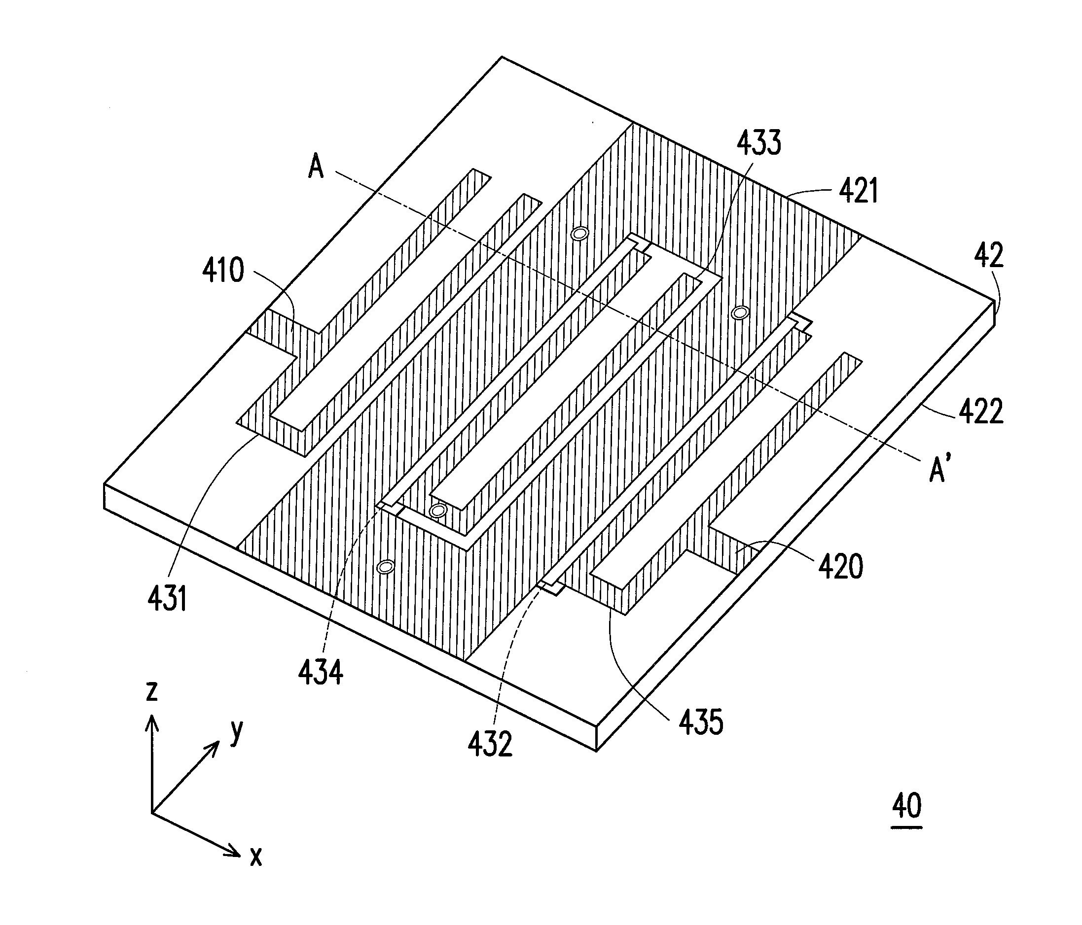
[0032]FIG. 4 is a schematic perspective view of a band-pass filter according to an embodiment of the invention. With reference to FIG. 4, a band-pass filter 40 includes a double-sided circuit board 42, an input terminal 410, an output terminal 420, and a plurality of resonance units 431-435. The double-sided circuit board 42 (also referred to as a double-sided board) has a first conductor layer 421 and a second conductor layer 422 disposed in an upper layer and a lower layer of the double-sided circuit board 42. In the present embodiment, the resonance units 431-435 are disposed in the first conductor layer 421 and the second conductor layer 422 respectively. It should be noted that, according to some embodiments of the invention, the number of the resonance units may be N, and N can be a positive integer greater than or equal to 3.

[0033]FIGS. 5A and 5B are used respectively in order to describe in detail the circuit design of the first conductor layer 421 and the second conductor l...


PUM


Abstract

A band-pass filter including a double-sided circuit board, an input terminal, an output terminal and a plurality of resonance units are provided. The double-sided circuit board includes a first conductor layer and a second conductor layer. The first conductor layer includes a grounded metal layer. The grounded metal layer includes one or more vias to connect to a grounded layer of the second conductor layer. The input terminal is disposed in the first conductor layer to receive a signal. The output terminal is disposed in the first conductor layer to output the filtered signal. The resonance units are disposed in the first and second conductor layers respectively, wherein the number of the resonance units is N, and N is a positive integer greater than or equal to 3.

Description

CROSS-REFERENCE TO RELATED APPLICATION[0001]This application claims the priority benefit of Taiwan application serial no. 101134168, filed on Sep. 18, 2012. The entirety of the above-mentioned patent application is hereby incorporated by reference herein and made a part of this specification.BACKGROUND[0002]1. Technical Field[0003]The invention relates generally to a technique of preventing electromagnetic radiation, and more particularly to a band-pass filter technique.[0004]2. Related Art[0005]Recently, as mobile communication techniques have advanced rapidly and the microwave communication industry has also grown in relative terms, the importance of high frequency circuit design cannot be ignored. With regards to wireless radio frequency (RF) terminal circuits and communication systems, the band-pass filter is one of the essential high frequency components in a mobile communication product. FIG. 1 is a schematic view of a conventional parallel coupled microstrip band-pass filter....

Claims


Application Information

Patent Timeline
IPC IPC(8): H01P1/203
CPCH01P1/205H01P1/20372
Inventor HUANG, CHIH-WEN
Owner TATUNG COMPANY
Why Eureka
Try Eureka