Position detecting device

Inactive Publication Date: 2014-03-20
WACOM CO LTD
View PDF15 Cites 79 Cited by
  • Summary
  • Abstract
  • Description
  • Claims
  • Application Information

AI Technical Summary

Benefits of technology

[0048]According to an embodiment of the present invention, a signal is transmitted from the stylus, and a coordinate position is detected by capacitive coupling. It is therefore possible to detect the position of either of the finger and the stylus by the transparent sensor disposed on the display device.
[0049]According to an embodiment of the present invention, two sets of receiving electrodes are selected simultaneously, and the differential amplifier is used to detect a difference between signals induced in these electrodes. It is thus possible to accurately detect and input the coordinate position of the finger and the stylus without being affected by noise produced by the display device.
[0050]According to an embodiment of the present invention, in touch detection, two sets of electrodes are selected as not only receiving side electrodes but also as driving side electrodes, and two driving signals shifted in phase from each other by 180° are supplied to the driving side ele

Problems solved by technology

This is because the sensor cannot be made transparent due to a need to feed a certain level of current through loop coils forming the sensor.
Therefore the sensor for detecting a stylus cannot be made in common with a sensor for detecting a position touched by a finger (the detection of a position touched by a finger will hereinafter be referred to as touch detection), which results in problems such as an increase in cost, complication of the structure of the position detecting device, and the like.
In addition, separate processing circuits are necessary for touch detection by a capacitive system and stylus detection by an electromagnetic induction system (detection of a pos

Method used


Image

  • Position detecting device
  • Position detecting device
  • Position detecting device

Examples


Embodiment Construction

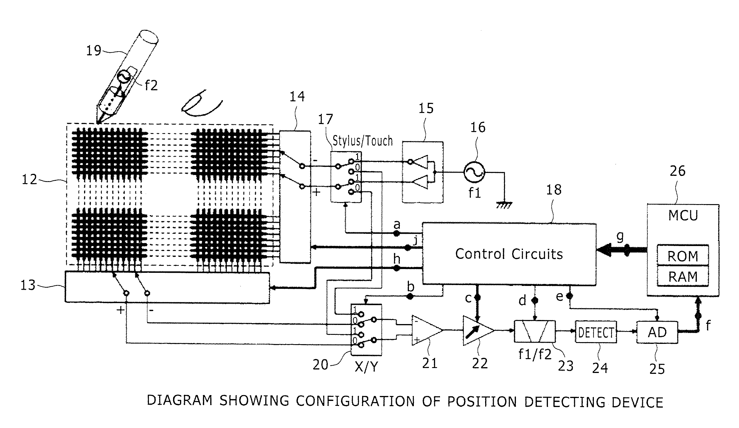
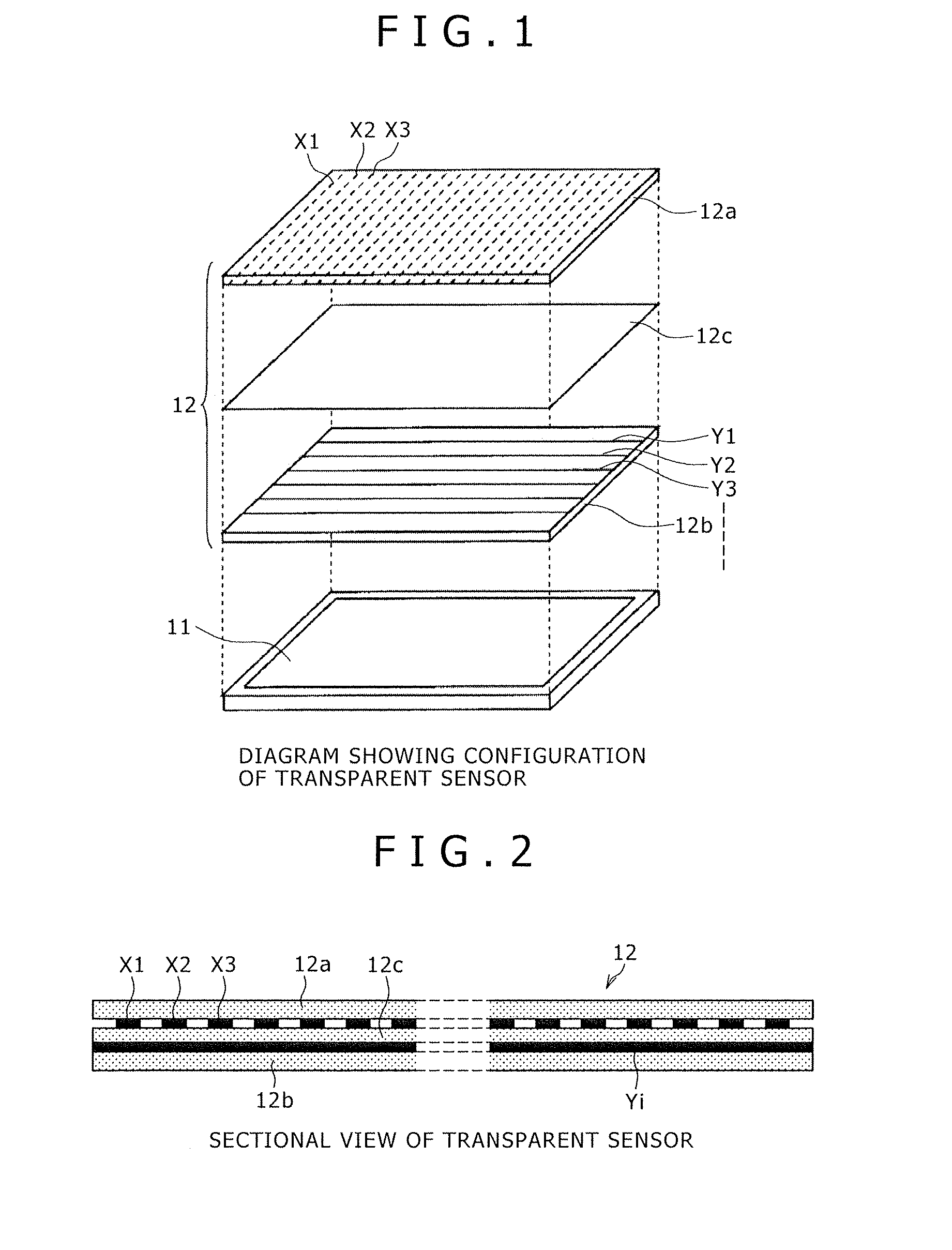
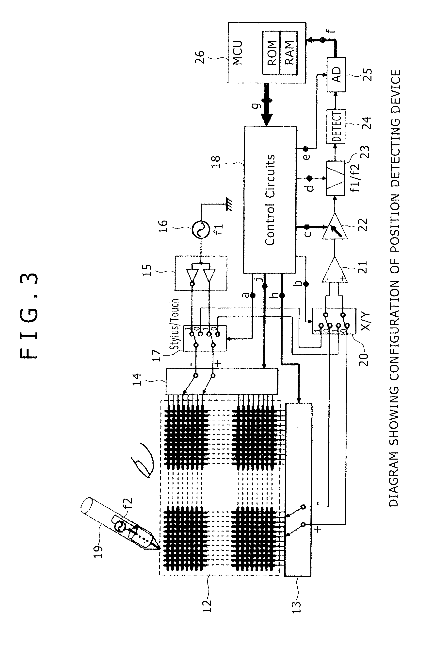
[0073]FIG. 1 is a diagram showing a configuration of a transparent sensor combined integrally with a display section in an embodiment of a position detecting device according to the present invention.

[0074]In FIG. 1, a reference numeral 11 denotes an LCD (Liquid Crystal Display) panel. A reference numeral 12 denotes the transparent sensor having electrodes formed by ITO (Indium Tin Oxide) (which electrodes will hereinafter be referred to as ITO electrodes). A reference 12a denotes a transparent glass formed by arranging a plurality of lines of ITO electrodes in an X-direction (which glass will hereinafter be referred to as an ITO glass). A reference 12b denotes an ITO glass formed by arranging a plurality of lines of ITO electrodes in a Y-direction orthogonal to the X-direction. A reference 12c denotes a PET (polyethylene terephthalate) film of a uniform thickness. The transparent sensor 12 is produced by opposing the respective ITO surfaces of the transparent glass 12a and the tran...


PUM


Abstract

A position detecting device detects both a finger and a stylus radiating an electric field. The device includes: a substantially transparent sensor disposed on a display device and formed by X-electrodes and Y-electrodes; an X-selecting circuit for selecting two sets of X-electrodes as a positive terminal and a negative terminal; a Y-selecting circuit for selecting two sets of Y-electrodes as a positive terminal and a negative terminal; a driving signal generating circuit for generating signals shifted in phase from each other by 180° as a positive signal and a negative signal; a differential amplifier for amplifying a difference between signals occurring in the positive terminal and the negative terminal selected by one, or respectively each, of the X-selecting circuit and the Y-selecting circuit; and a balanced switching circuit for switching connection of the positive terminal and the negative terminal to the driving signal generating circuit or to the differential amplifier.

Description

CROSS-REFERENCE TO RELATED APPLICATION[0001]The present application claims priority under 35 U.S.C. 119(a) to Japanese Patent Application No. 2012-206556, filed Sep. 20, 2012, which is incorporated by reference herein.BACKGROUND[0002]1. Technical Field[0003]The present invention relates to a transparent position detecting device that is disposed on a front surface of a display device and which enables operation with both of a finger and a pen type position indicator (pen type position indicator will hereinafter be referred to as a stylus).[0004]2. Description of the Related Art[0005]Tablet type information terminals including a touch panel have recently come into frequent use. Some devices of this kind enable input with a stylus in order to facilitate the input of handwritten characters and the drawing of pictures, illustrations, and the like, which are difficult with a finger. A method disclosed in Patent Document 1 (Japanese Patent Laid-Open No. Sho 63-70326) is widely used as a p...

Claims


Application Information

Patent Timeline
IPC IPC(8): G06F3/044G06F3/0354
CPCG06F3/03545G06F3/044G06F2203/04104G06F3/0445G06F3/04182G06F3/04184G06F3/0446G06F3/0442
Inventor KATSURAHIRA, YUJI
Owner WACOM CO LTD
Why Eureka
Try Eureka