
Method for fabricating optical micro structure and applications thereof

a technology of optical microstructure and fabrication method, which is applied in the direction of electrical equipment, semiconductor devices, radio frequency controlled devices, etc., can solve the problems of inability to achieve the effect of reducing the optical path affecting the quanta efficiency of the fsi image sensor, and requiring additional procedures

Active Publication Date: 2014-03-20
UNITED MICROELECTRONICS CORP
View PDF6 Cites 1 Cited by
  • Summary
  • Abstract
  • Description
  • Claims
  • Application Information

AI Technical Summary

Benefits of technology

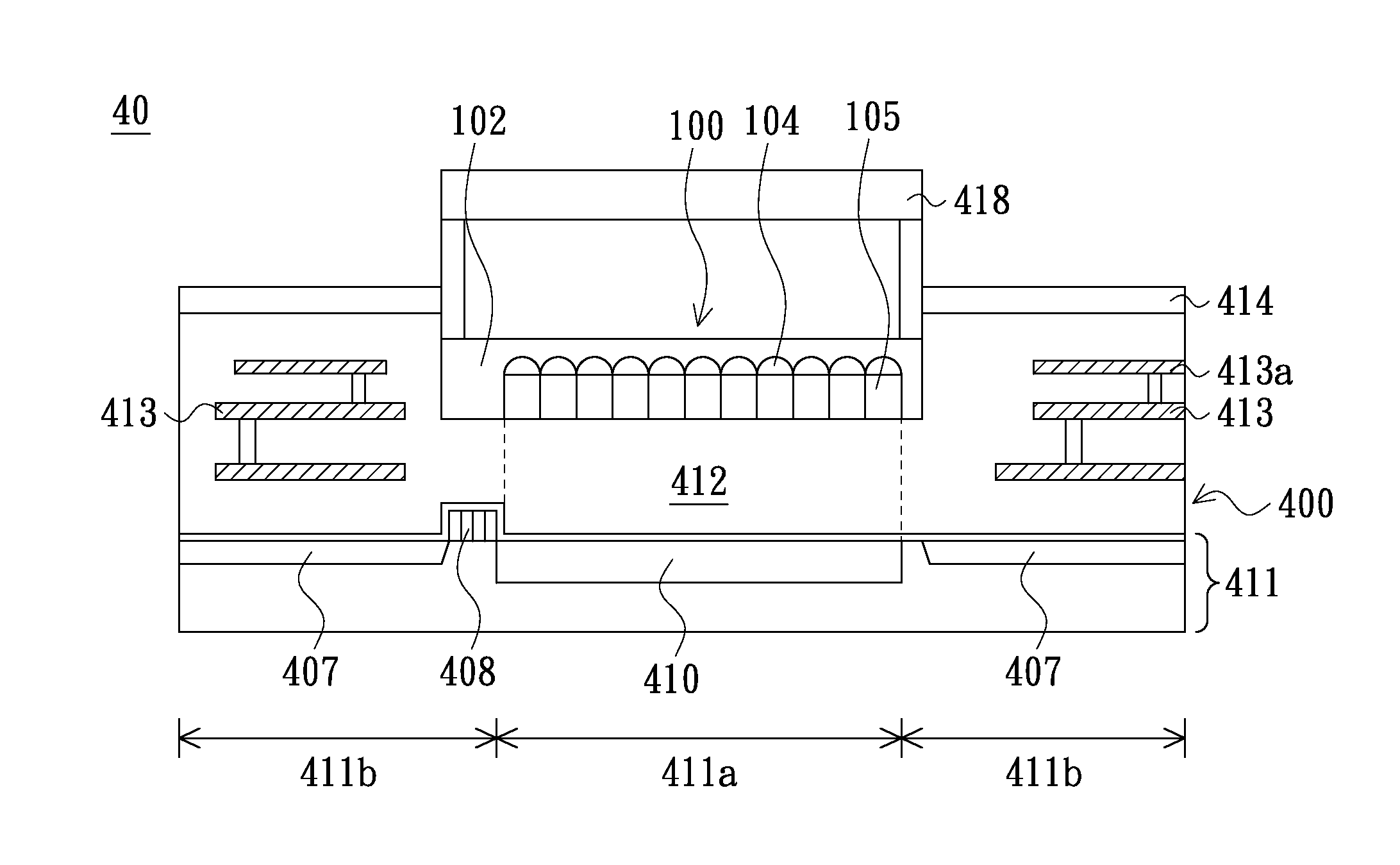
The present invention provides an improved method of fabricating an image sensor with a color filter. The color filter is formed on a separate substrate and is engaged with the image sensing device afterward, allowing for a simpler and more cost-effective packaging process. The use of a pre-planarized color filter and an optical microstructure fabrication method can improve the efficiency and resolution of the image sensor while reducing cross-talk and fabrication costs. The resulting image sensor has a performance similar to that of a typical BSI image sensor but at a significantly lower cost.

Problems solved by technology

However, fabricating a backside illuminated image sensor requires additional procedures in contrast to fabricating a front-side illuminated image sensor.
Besides, the existence of the handle wafer may obstruct the subsequent packaging process from making the wiring bond pad of the inner-metal layer, thus some additional through silicon vias (TSV) may be needed.
Accordingly, fabricating a backside illuminated image sensor is more complicated and costly than fabricating a front-side illuminated image sensor.
However, since the rough and unevenness surface of the embedded color filter may adversely affect the subsequent process and yield, thus the embedding depth of the color filter may be limited.
These problems may get worse, as the current front-side illuminated image sensor is required to provide more and more resolution and small pixel size.

Method used


Image

  • Method for fabricating optical micro structure and applications thereof
  • Method for fabricating optical micro structure and applications thereof
  • Method for fabricating optical micro structure and applications thereof

Examples


Embodiment Construction

[0032]Detail descriptions of several embodiments eligible to exemplify the features of making and using the present invention are disclosed as follows. It must be appreciated that the following embodiments are just example, but not used to limit the scope of the present invention. Wherever possible, the same reference numbers are used in the drawings and the description to refer to the same or like parts.

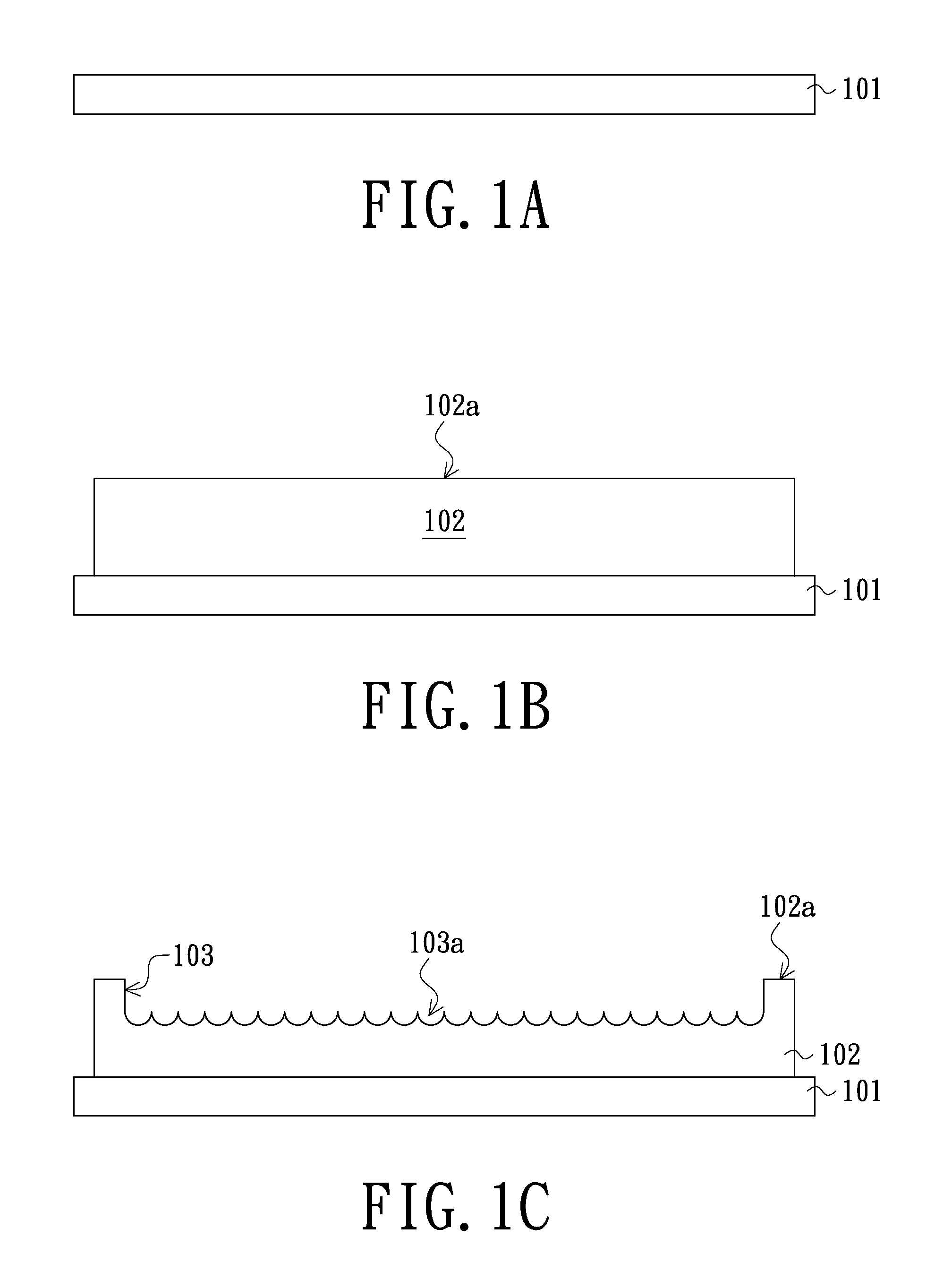
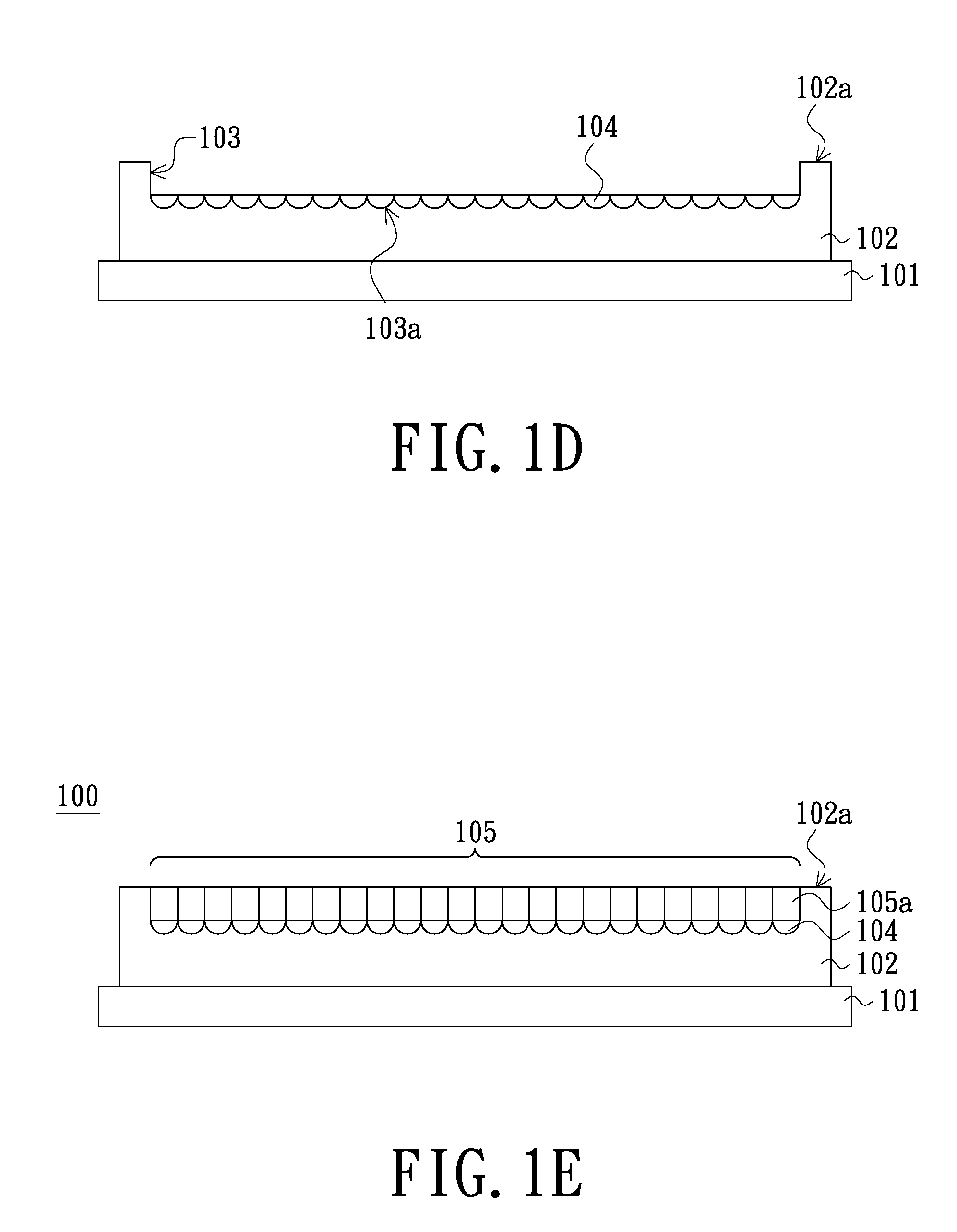
[0033]One of the objects of the present invention is to fabricate an improved image sensor having an optical microstructure 100. FIGS. 1A to 1E illustrate cross-sectional views of the processing structures for fabricating an optical microstructure 100 in accordance with one embodiment of the present invention.

[0034]The method for fabricating the optical microstructure 100 comprises steps as follows: A working substrate101 (shown in FIG. 1A) is provided. In some embodiments of the present invention, the working substrate 101 is a glass substrate, a silicon substrate or a silicon wafe...


PUM

PropertyMeasurementUnit
transparentaaaaaaaaaa
refraction ratioaaaaaaaaaa
depthaaaaaaaaaa

Abstract

A method for fabricating an image sensor, wherein the method comprises steps as follows: Firstly, a transparent substrate is formed on a working substrate. Pluralities of micro lens are formed in the transparent substrate, wherein the lenses have a refraction ratio differing from that of the transparent substrate. Subsequently, a color filter is formed on the lenses. Afterward, the color filter is engaged with an image sensing device by flipping around the working substrate.

Description

CROSS-REFERENCE TO RELATED APPLICATION[0001]This application is a divisional application of U.S. application Ser. No. 13 / 175,989, filed on Jul. 5, 2011, and now pending. The entirety of the above-mentioned patent application is hereby incorporated by reference herein and made a part of this specification.FIELD OF THE INVENTION[0002]The present invention relates to a fabricating method of an optical microstructure and the applications thereof, and more particularly to a method for fabricating an optical microstructure applying for manufacturing an image sensor and the applications thereof.BACKGROUND OF THE INVENTION[0003]By virtue of the technical improvement and increased requirement of consumer electrics with image processing functions, such as digital cameras, scanners or smart phones, the demand for image sensors is continually growing.[0004]Generally, image sensors can be divided into two types, front-side illuminated image sensors and backside illuminated image sensors.[0005]Si...

Claims


Application Information

Patent Timeline
Patent Type & Authority Applications(United States)
IPC IPC(8): H01L27/146
CPCH01L27/14685H01L27/14618H01L27/14625H01L27/14627H01L2924/0002Y10T29/49H01L2924/00
Inventor YU, CHENG-HUNG
Owner UNITED MICROELECTRONICS CORP
Learn More