System and Method for Magnetic Field Data Compression

a magnetic field and data compression technology, applied in the field of magnetic field data compression, can solve the problems of loss of useful information, varying the degree of noise and stability of the magnetic component itself, and the amount of magnetic interference that is typically present, so as to eliminate the variation between magnetic samples

Active Publication Date: 2014-03-20
XSENS HLDG BV
View PDF15 Cites 75 Cited by
  • Summary
  • Abstract
  • Description
  • Claims
  • Application Information

AI Technical Summary

Benefits of technology

[0012]The method then entails rotating to a common time instant one or more of the plurality of magnetic field samples collected within a time interval using the orientation of the sensing unit at each of the plurality of points in time, estimated by means of the other sensing modality, in order to produce a magnetic samples set that eliminates variations between magnetic samples due to changes in orientation of the sensor unit within such time interval. The magnetic samples corrected for the sensor rotation in such interval, are used to calculate magnetic field related information specific to the given time interval and the magnetic field related information is communicated to a receiver at a rate lower than the sample rate.

Problems solved by technology

Moreover, magnetic disturbances may be caused by the movement of the device on which the magnetometer is integrated, and there may be varying degrees of noise and stability of the magnetic component itself, etc.
Additionally, when the magnetometer is integrated with other circuitry or different electronic components, as common in consumer electronics devices (for example smart-phones, tablets, etc.), some amount of magnetic interference is typically present, caused by e.g. inductors, currents from the main power supply tracks, etc.
However, in the case of low communication rates between the IMU and the Application Processor (AP) side of the device to conserve system resources, or in the presence of rapidly changing magnetic fields, a single magnetic field update may not be sufficient to accurately describe the magnetic field, resulting in loss of useful information.
Similarly, in first responder applications, the data-link might be unreliable.
Failures in data reception can result in coarser or variable time resolution between measurement updates (this is a general problem for wireless inertial sensor applications as well).
Moreover, low update rates lead to decreased computational demands, since computationally costly fusion algorithms can run at much lower, user selectable, or application driven rates, while the goal is to preserve the same accuracy that could be achieved when processing at high ODRs.
However, no system to optimally compress and “pack” together relevant information from magnetometers yet exists.

Method used


Image

  • System and Method for Magnetic Field Data Compression
  • System and Method for Magnetic Field Data Compression
  • System and Method for Magnetic Field Data Compression

Examples


Embodiment Construction

[0023]Preferred embodiments of the present disclosure will be described herein below with reference to the accompanying drawings. In the following description, well-known functions or constructions are not described in detail to avoid obscuring the present disclosure in unnecessary detail. A brief overview of the system of interest will be given before presenting a detailed discussion of the various system components and functions.

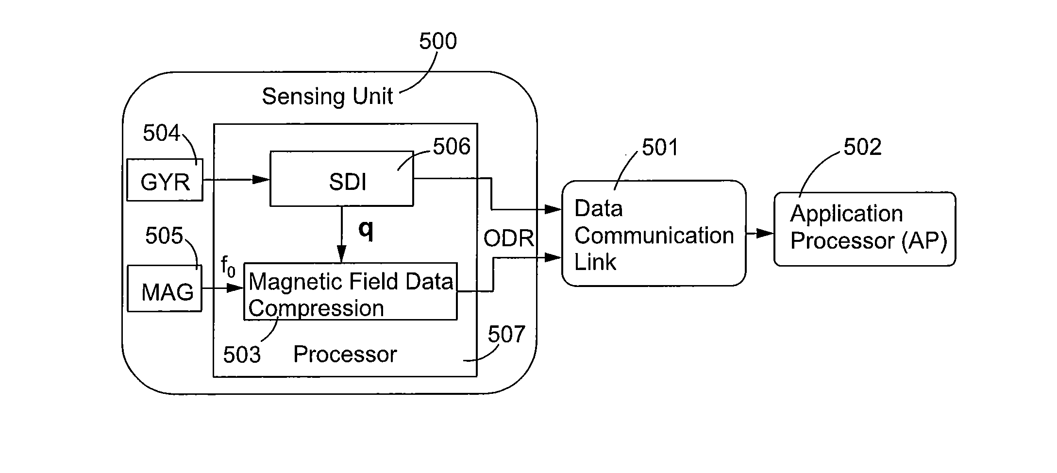
[0024]In an embodiment of the disclosed principles, instead of simply sending the last known sample from the 3D magnetometer to the AP, starting from the original high rate samples collected within the entire time interval since the last data was sent to the AP, a low rate output sample is computed that gives all the relevant magnetic field information about such time interval. In this way, magnetometer information marginalization is enabled.

[0025]Thus, in particular, a 3D magnetometer is sampled at high frequency at the sensor-side. Using the angular velo...


PUM


Abstract

A technique for calculating magnetic field information from a magnetic sensor employs a sensing unit containing the magnetic sensor and another sensor capable of providing a measure of change in orientation. The method includes sampling a magnetic field at points in time and sampling the other sensor at each point in time. The method then entails rotating to a common time instant the magnetic field samples using the orientation of the sensing unit estimated by means of the other sensing modality in order to eliminate variations between magnetic samples due to changes in orientation of the sensor unit within such time interval. The magnetic samples, corrected for the sensor rotation in such interval, are used to calculate magnetic field related information specific to the given time interval and the magnetic field related information is communicated to a receiver at a rate lower than the sample rate.

Description

TECHNICAL FIELD OF THE DISCLOSURE [0001]The present disclosure relates to a system and method for calculating magnetic field related information from a set of high-rate magnetometer samples collected within a given time interval. Such magnetic field information can be transmitted to a receiver application processor at a rate lower than the original sample rate, minimizing the data communication requirements when magnetometers are used for example in orientation, position tracking, or SLAM applications.BACKGROUND OF THE DISCLOSURE [0002]A common use of magnetometers is in combination with an inertial based measurement unit (IMU). The magnetic field is generally used to improve the position and orientation detection, especially with respect to the heading component, which would otherwise suffer from unbounded drift resulting from the integration of angular velocity in orientation. The use of an external magnetic field as a reference can serve to limit or eliminate this drift.[0003]Ano...

Claims


Application Information

Patent Timeline
Patent Type & Authority Applications(United States)
IPC IPC(8): G01C17/02G01P15/00G01P3/00
CPCG01C17/02G01P15/00G01P3/00G01C17/38G01R33/0023G01R33/0064H03M7/3059H03M7/3062
Inventor BELLUSCI, GIOVANNISLOT, PIETER LAURENSLUINGE, HEDRIK JOHANNES
Owner XSENS HLDG BV
Why Eureka
Try Eureka