Winch Braking Device

Active Publication Date: 2014-03-27
SUMITOMO HEAVY INDUSTRIES CONSTRUCTION CRANE CO LTD
View PDF4 Cites 13 Cited by
  • Summary
  • Abstract
  • Description
  • Claims
  • Application Information

AI Technical Summary

Benefits of technology

[0007]However, there is an issue yet to be addressed with regard to the braking device disclosed in the publication in that as the characteristics of the reaction force-imparting element such as a vis

Problems solved by technology

However, there is an issue yet to be addressed with regard to the braking device disclosed in the publication in that as the characteristics of the reaction force-imparting element such as a viscoe

Method used


Image

  • Winch Braking Device
  • Winch Braking Device
  • Winch Braking Device

Examples


first embodiment

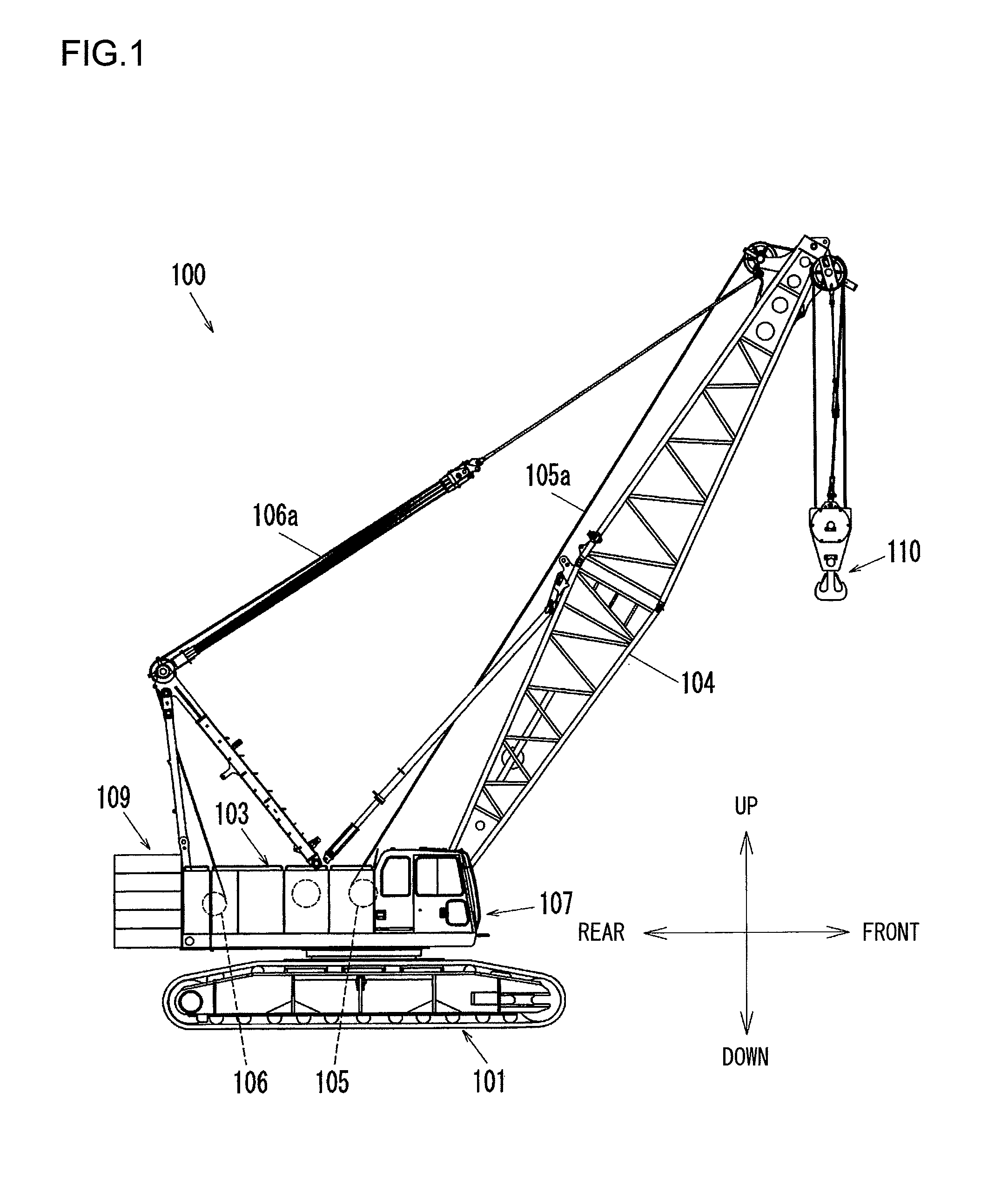
[0026]FIG. 1 presents an external view of a crane 100 equipped with a winch braking device achieved in the first embodiment of the present invention in a side elevation. The directional terms up / down and front / rear used in the following description are defined, as indicated in the figure, in reference to the attitude of the crane shown in FIG. 1. The crane 100 includes a traveling undercarriage 101, a revolving superstructure 103 rotatably disposed upon the traveling undercarriage 101 via a revolving ring, and a boom 104 axially supported at the revolving superstructure 103 so as to be allowed to rotate. An operator's cab 107 is located at the front of the revolving superstructure 103, whereas a counterweight 109 is mounted at the rear of revolving superstructure 103. A hoisting drum 105, which is a winch drum engaged in hoisting operation, and a derricking drum 106, which is a winch drum engaged in boom derricking operation, are installed in the revolving superstructure 103.

[0027]A...

second embodiment

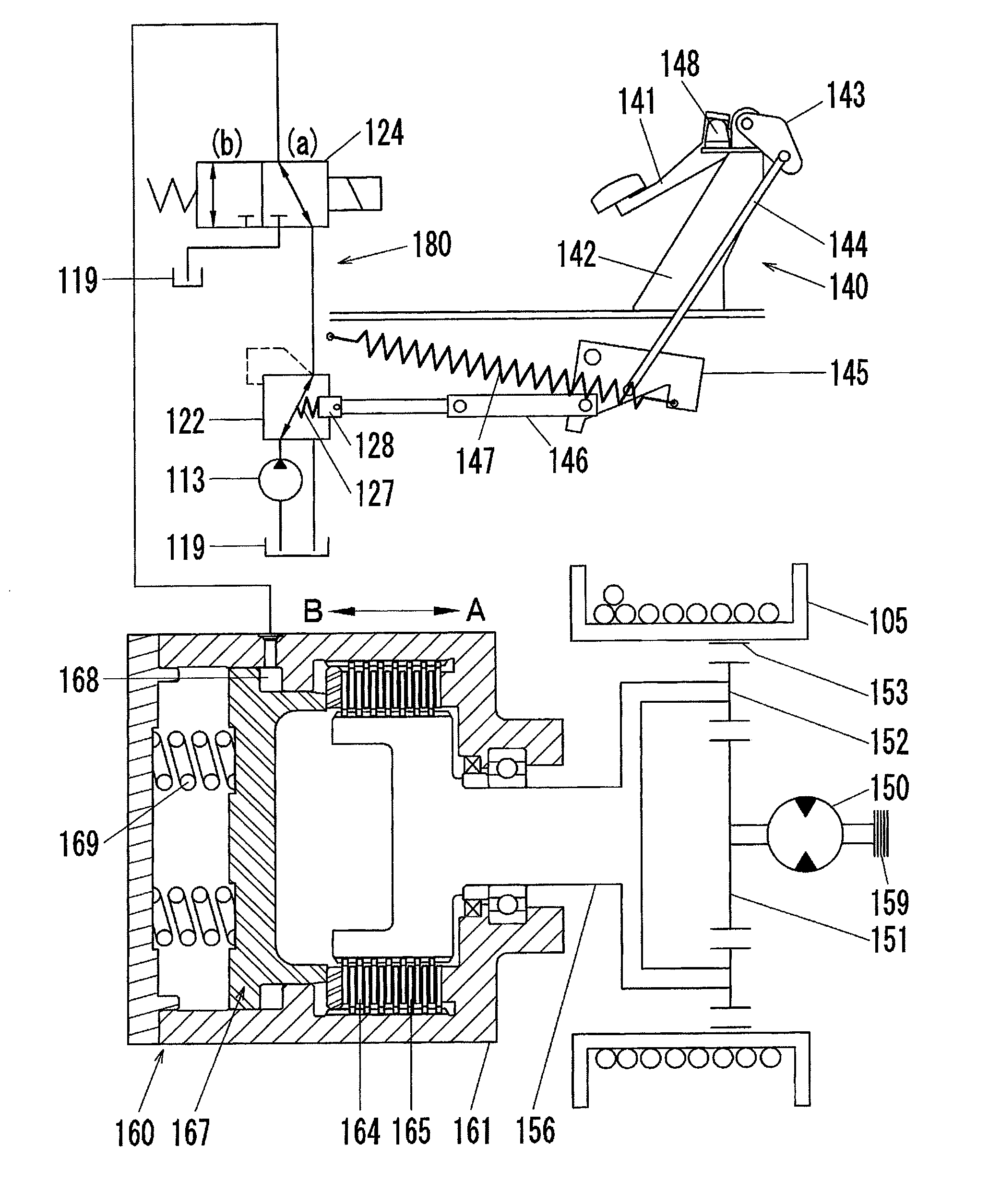
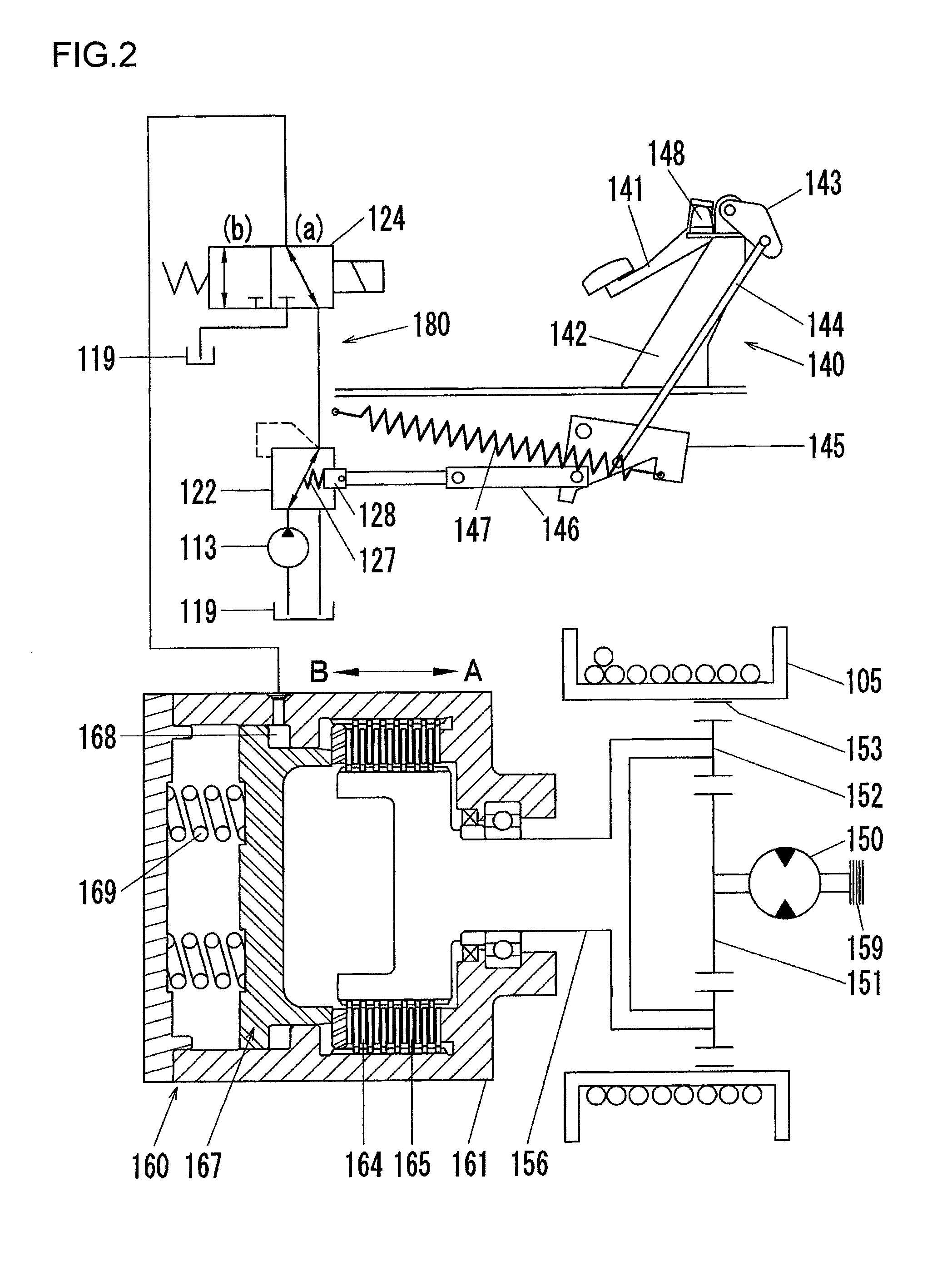
[0081]In reference to FIG. 11, the winch braking device achieved in the second embodiment will be described. FIG. 11 is a hydraulic circuit diagram showing the structure of the winch braking device achieved in the second embodiment of the present invention. The following explanation will focus on features distinguishing the second embodiment from the first embodiment, with the same reference numerals assigned to components identical or equivalent to those in the first embodiment.

[0082]The braking device, having been described in reference to the first embodiment, includes the suspended brake pedal device 140 and the negative type brake 160. In contrast, the braking device achieved in the second embodiment includes a floor-mounted (organ type) brake pedal device 240 and a positive type brake 260.

[0083]Namely, while the friction disks are pressed in contact by applying a force to the brake disk 167 via the spring 169 in the first embodiment (see FIG. 2), the friction disks are pressed...


PUM


Abstract

A winch braking device includes: a brake; a brake pedal; a reaction force-imparting element that imparts a reaction force to the brake pedal; a rotation link that rotates by interlocking with the foot operation at the brake pedal; a brake valve linked to the rotation link, that applies a secondary pressure to the brake in response to the foot operation at the brake pedal; and a tension spring, with one end thereof attached to the vehicle body at a predetermined position and another end thereof attached to the rotation link, that applies a force to the brake pedal along a direction opposite a direction of the foot operation. As the foot operation is performed at the brake pedal, the tension spring extends and a shortest distance between a rotational center of the rotation link and a central axis of the tension spring becomes smaller.

Description

INCORPORATION BY REFERENCE[0001]The disclosure of the following priority application is herein incorporated by reference: Japanese patent application No. 2012-210977 filed Sep. 25, 2012BACKGROUND OF THE INVENTION[0002]1. Field of the Invention[0003]The present invention relates to a braking device for a winch installed in a crane or the like.[0004]2. Description of Related Art[0005]It is standard practice in the related art to use a dynamic hydraulic braking device such as that disclosed in Japanese laid open patent publication No. 2003-48689 as a braking device for a winch installed in a crane or the like, which is required to exert a significant braking force without requiring a great operating force.[0006]The publication cited above discloses a winch braking device that includes a reaction force-imparting element providing a damping effect, which may be constituted of a viscoelastic material, disposed at a brake pedal. The winch braking device disclosed in the publication is capa...

Claims


Application Information

Patent Timeline
IPC IPC(8): B66D5/28
CPCB66D5/28B66D5/14B66D5/26
Inventor MIYAZAKI, TADASHI
Owner SUMITOMO HEAVY INDUSTRIES CONSTRUCTION CRANE CO LTD
Why Eureka
Try Eureka