Method for rationalising a chain of electrical components of an aircraft, implementation architecture and corresponding aircraft
a technology of electrical components and implementation architecture, applied in the direction of electric devices, machines/engines, transportation and packaging, etc., can solve the problems of unsuitable driving of energy supply architectures on the basis described above, excessive use of motors and/or generators for electrical coordination, complex architecture, etc., and achieves not very economical energy use.
- Summary
- Abstract
- Description
- Claims
- Application Information
AI Technical Summary
Benefits of technology
Problems solved by technology
Method used
Image


Examples
Embodiment Construction
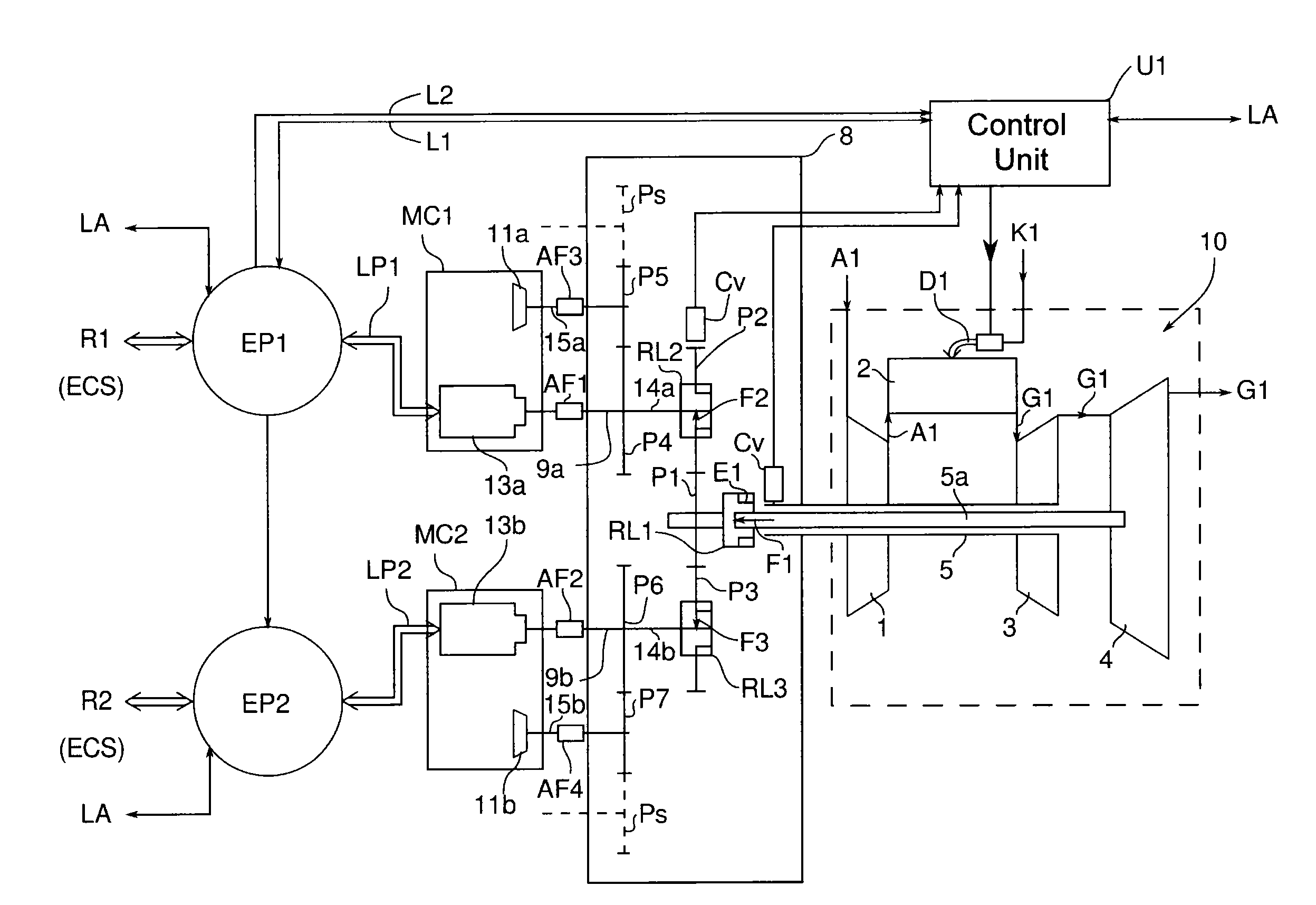
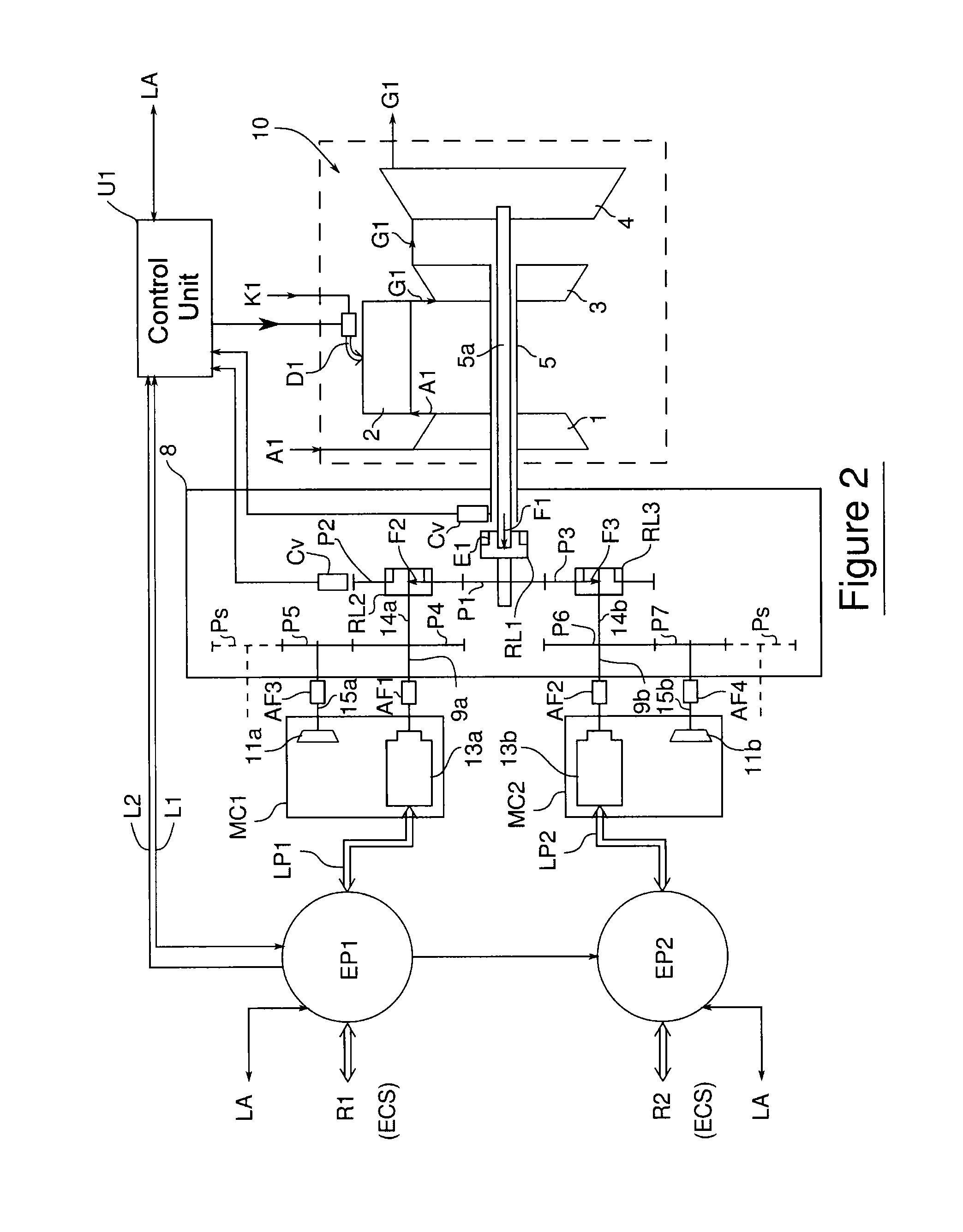
[0019]The aim of the invention is to overcome these drawbacks and, in particular, to produce an architecture that is able to rationalise the electrical distribution between different components of an aircraft, in order to reduce the number of components, the space occupied, mass and cost, while ensuring a high degree of reliability.
[0020]In order to do this, the invention proposes to optimise the power supply via a method of operation of the APUs' electrical supply systems that is adapted to be reversible. This method of operation allows an adaptation, in the event of a failure of the APU or of the system for supplying pneumatic or hydraulic power.
[0021]More specifically, the present invention relates to a method for rationalising a chain of components for transmission of electrical power of an aircraft that has an auxiliary power unit (APU), main engines and systems that are end consumers of electrical, pneumatic and / or hydraulic power managed by dedicated control systems. The APU ...
PUM
 Abstract
Description
Claims
Application Information