

Rotating electrical machine and electric power steering system using the same
a technology of electric power steering and electric motor, which is applied in the direction of dynamo-electric machines, electrical devices, windings, etc., can solve the problems of difficult coils to increase the space factor of coils within the stator slot of motors, and cannot support up to a high rotational speed region, so as to reduce torque ripple and reduce cogging torque
- Summary
- Abstract
- Description
- Claims
- Application Information
AI Technical Summary
Benefits of technology
Problems solved by technology
Method used
Image

Examples
first embodiment
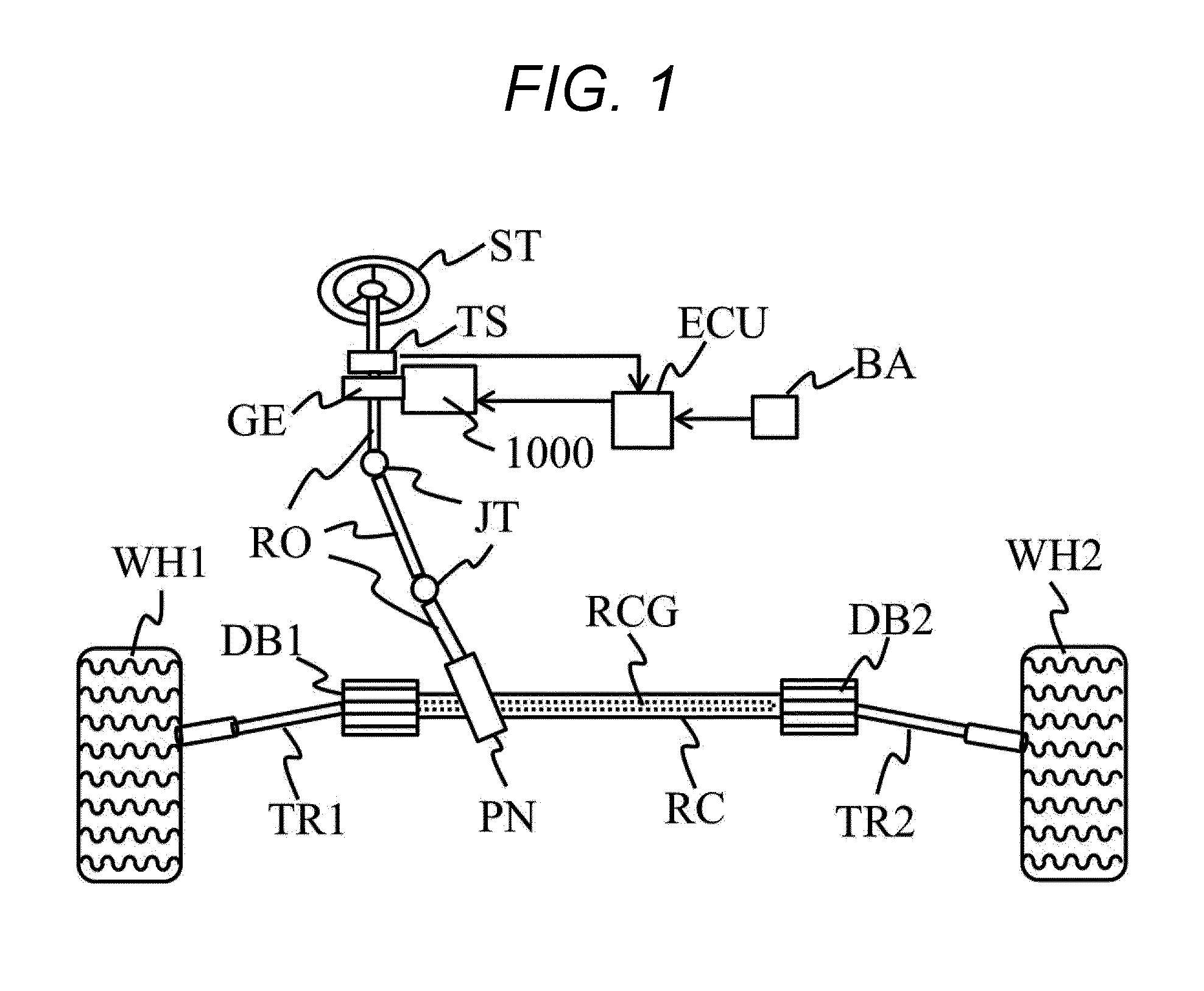
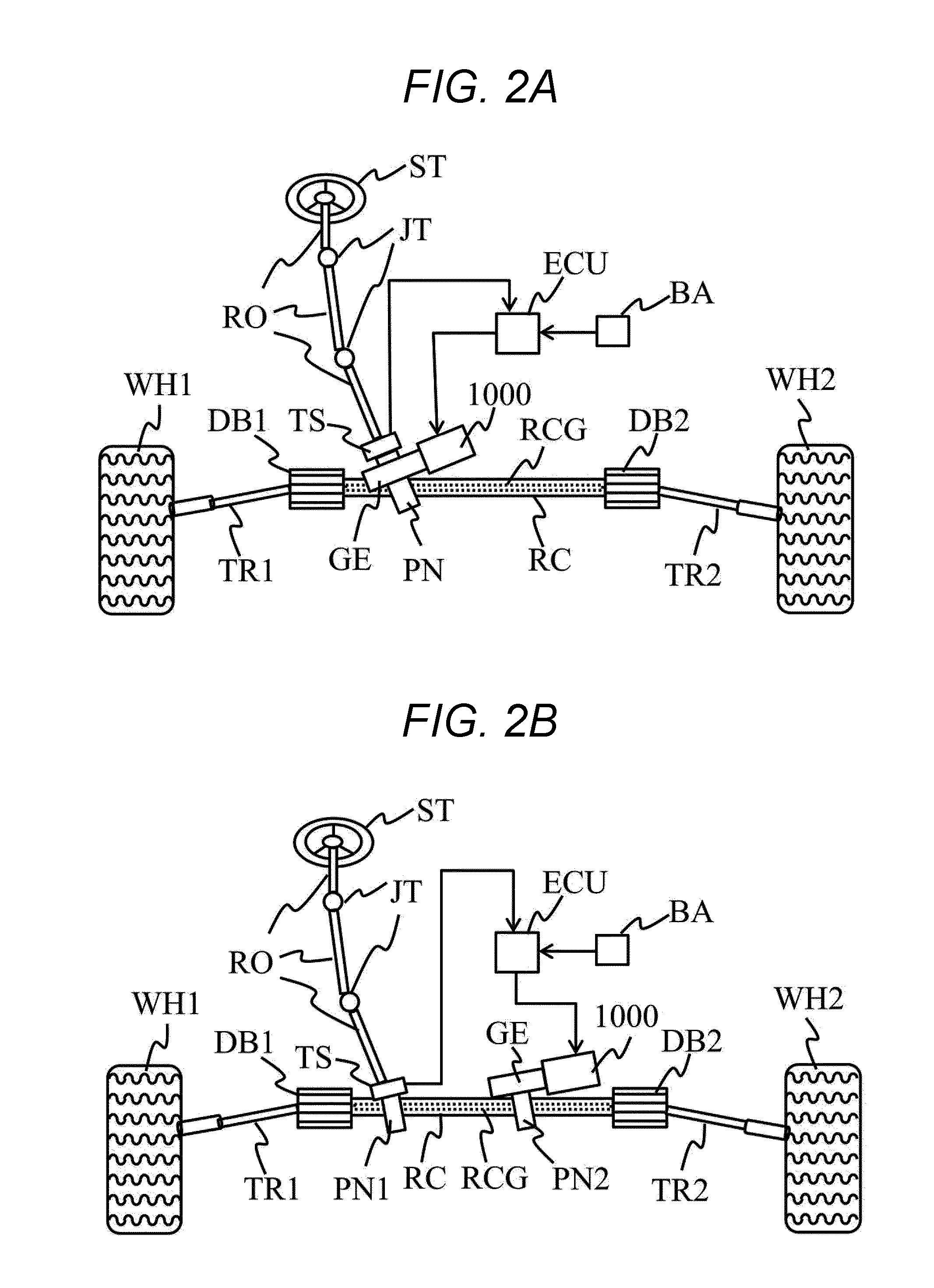
[0027]A first embodiment of the present invention will now be described. The operating principle of an electric power steering system according to the present embodiment will be described first with reference to FIGS. 1 to 3. An electric power steering system according to the present embodiment includes: an in-vehicle battery; a control unit which converts DC power supplied from the in-vehicle battery via a wire harness into polyphase AC power and controls the output thereof in accordance with torque applied onto a steering; and an electric power steering motor which is driven by the AC power supplied from the control unit in order to output torque to assist the steering. The electric power steering motor includes a frame, a stator fixed to the frame, and a rotor disposed in opposed relation to the stator by way of an air gap, the stator including a stator core and a polyphase stator coil incorporated into the stator core. The stator core includes an annular back core portion and a ...
second embodiment
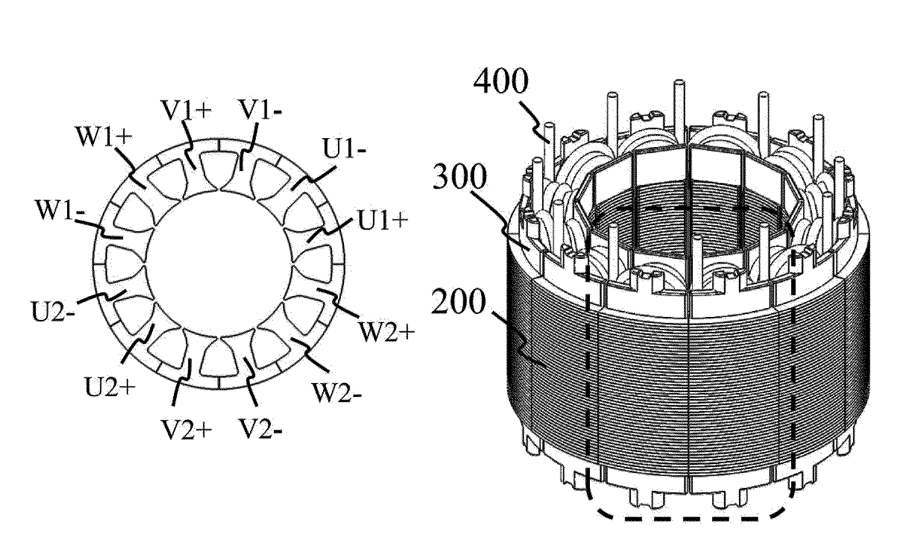
[0044]A second embodiment of the present invention will now be described with reference to FIGS. 7A and 7B. FIG. 7A is a diagram in which a stator core 200, a bobbin 300, and a stator coil 400 are assembled together. The stator coil 400 here is formed of a square wire or a rectangular wire. The square wire or the rectangular wire is suitable for a regular winding of the stator coil, by which one can expect a space factor to be increased. Compared with a round wire, moreover, the coil formed of the square or the rectangular wire is not displaced easily within a slot after being wound, which is comparatively convenient in terms of manufacturing. FIG. 7B is a diagram in which adjacent coils in the same phase are wound in a continuous manner. The stator coil is continuously wound around two teeth from a winding start end 401 to a winding finish end 402. As with the first embodiment, the coil makes n turns around one of the teeth, and the coil in the same phase makes the number of turns ...
third embodiment
[0045]A third embodiment of the present invention will now be described with reference to FIGS. 8A and 8B. FIG. 8A is a diagram in which a stator core 200, a bobbin 300, and a stator coil 400 are assembled together. FIG. 8B is a diagram in which adjacent coils in the same phase are wound in a continuous manner. The stator coil is wound from a winding start end 401 making n turns, and then moves to the adjacent tooth around which the stator coil makes m turns in a continuous manner in a direction opposite to the adjacent tooth, the m turns corresponding to the number of turns that is greater or less than n turns by 0.5 turns. Note that each of the n and the m takes an integer value. As a result, a slot space can be used effectively to improve a space factor as well as the flexibility in design. As with the first and the second embodiments, the number of turns can be selected by a small increment so that the flexibility in design can be drastically increased. In this case, moreover, t...
PUM
 Abstract
Description
Claims
Application Information