Control device for rotary machine
a control device and rotary machine technology, applied in the direction of motor/generator/converter stopper, dynamo-electric gear control, dynamo-electric converter control, etc., can solve the problems of insufficient reliable detection of the rotor position and the inability to accurately estimate the rotor position, so as to achieve the effect of detecting stably and accurately
- Summary
- Abstract
- Description
- Claims
- Application Information
AI Technical Summary
Benefits of technology
Problems solved by technology
Method used
Image
Examples
embodiment 1
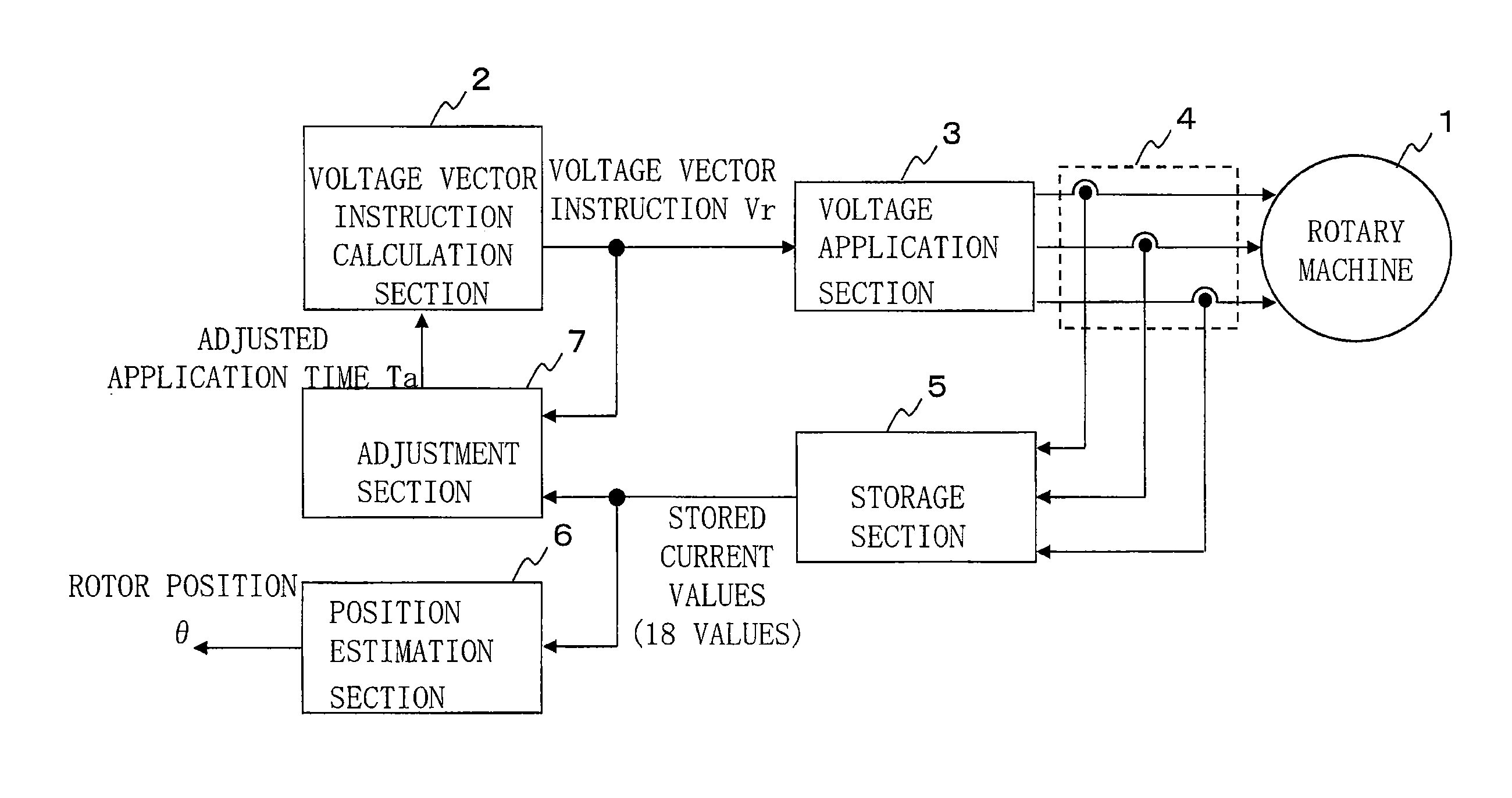
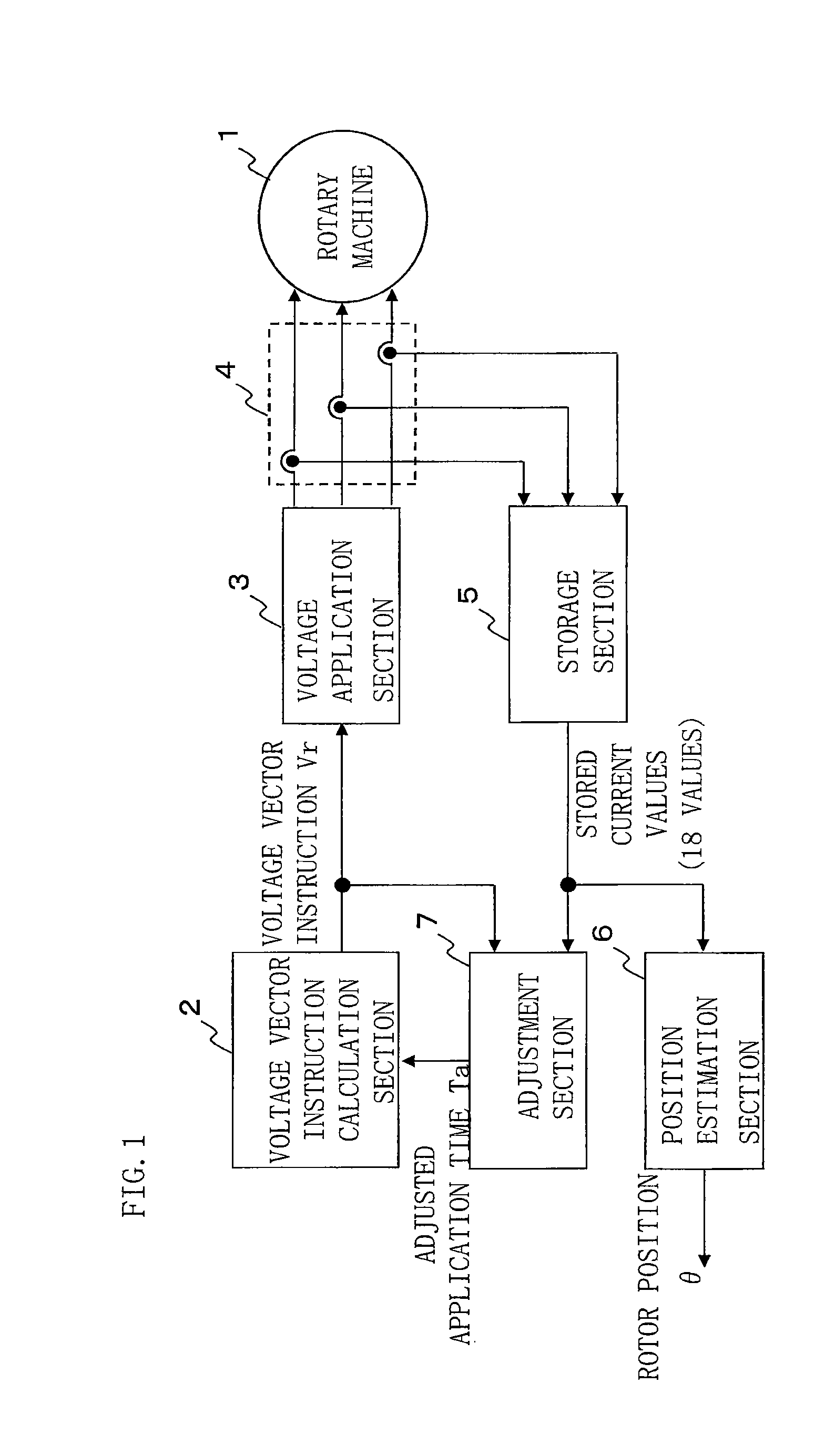
[0027]FIG. 1 is a configuration diagram of a control device for rotary machine according to embodiment 1 of the present invention. In FIG. 1, the rotary machine 1 has three-phase windings for U phase, V phase, and W phase, and here, is a permanent magnet rotary machine in which a permanent magnet is provided on a rotor. The rotary machine 1 is connected to a voltage application section 3 for applying voltage, such as an inverter. The voltage application section 3 applies a voltage vector based on a voltage vector instruction Vr inputted thereto, to the rotary machine 1. A current detection section 4 for detecting winding current flowing in the rotary machine 1 is connected between the voltage application section 3 and the rotary machine 1.
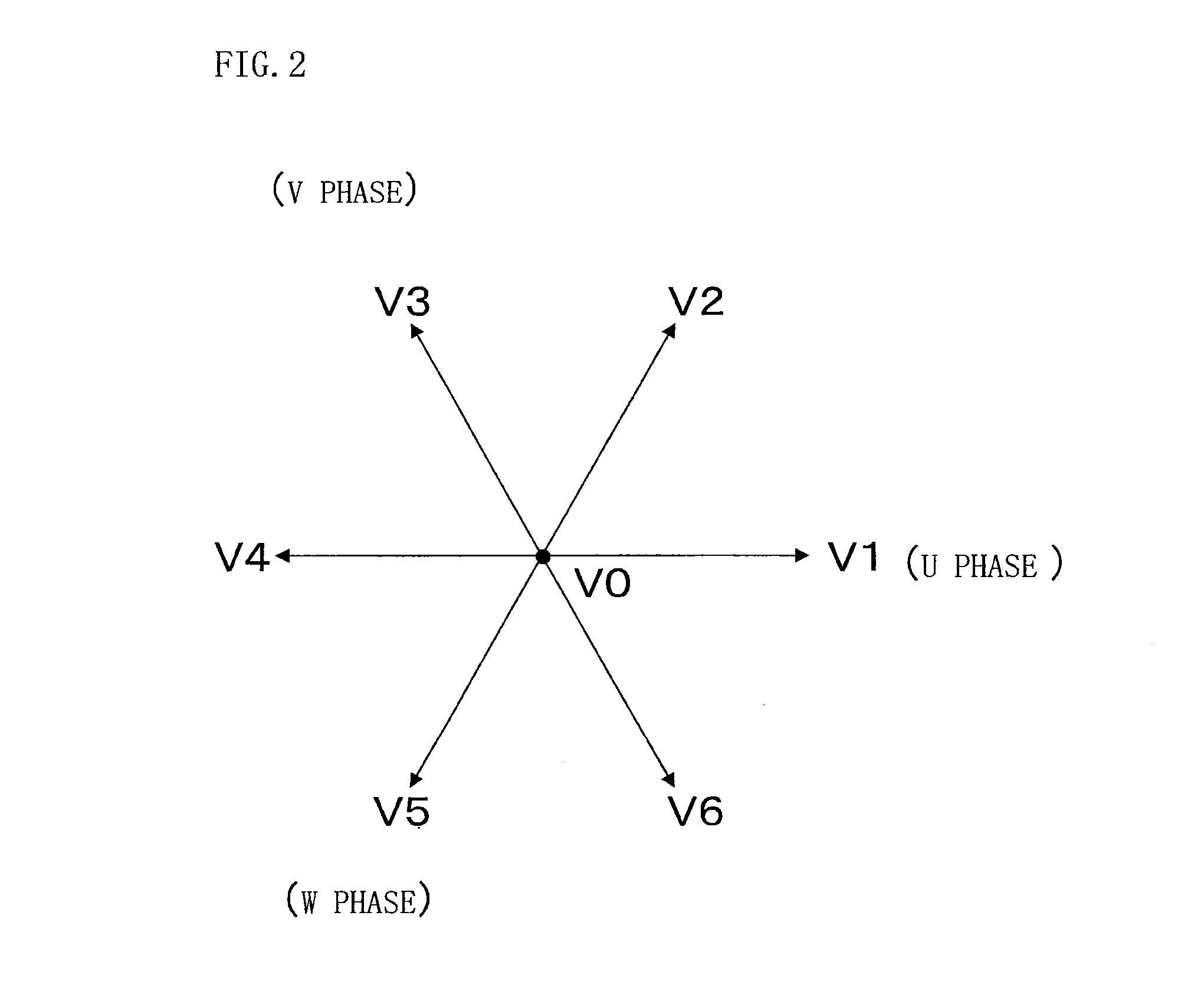
[0028]A voltage vector instruction calculation section 2 sequentially applies voltage vector instructions V1 to V6 which are separated at 60-degree intervals as shown in FIG. 2, with a zero voltage vector instruction V0 being interposed therebetwee...
embodiment 2
[0063]In the above embodiment 1, for adjustment of the application time Ta of the voltage vector instruction, the application time of the voltage vector instruction is set at an arbitrary value Tm, and the value of Tm is changed as appropriate, whereby the minimum necessary application time setting value Ta that allows estimation of the rotor position is obtained. On the other hand, the present embodiment 2 is intended to, by gradually increasing the application time of the voltage vector instruction from a value close to zero upon the setting, make it possible to calculate the application time Ta of the voltage vector instruction while reducing a time needed for automatic adjustment and making current flowing in the rotary machine 1 as small as possible.
[0064]The configuration of the present embodiment 2 is the same as in embodiment 1 shown in FIG. 1, and matters such as the way of calculating the magnitude of the differential admittance are also the same. Only the setting method f...
embodiment 3
[0073]It is desirable that the predetermined differential admittance threshold value ΔYlev of the above embodiment 1 or 2 is set to the magnitude of the differential admittance that allows the position estimation section 6 to estimate the position accurately and does not allow current flowing in the rotary machine 1 to become excessively large. Therefore, for example, if sufficient magnetic saturation occurs when the summed current value is 10% of the rated current value of the rotary machine 1, the differential admittance corresponding to the case where the summed current value is 10% of the rated current value is set as the differential admittance threshold value ΔYlev. Such a differential admittance threshold value ΔYlev can change depending on the type or the capacity of the rotary machine 1.
[0074]Therefore, in the case where, for example, the differential admittance threshold value ΔYlev is set with reference to the rated current value of the rotary machine 1, and the position ...
PUM
 Abstract
Description
Claims
Application Information
 - R&D
- Intellectual Property
- Life Sciences
- Materials
- Tech Scout
- Unparalleled Data Quality
- Higher Quality Content
- 60% Fewer Hallucinations
Browse by: Latest US Patents, China's latest patents, Technical Efficacy Thesaurus, Application Domain, Technology Topic, Popular Technical Reports.
© 2025 PatSnap. All rights reserved.Legal|Privacy policy|Modern Slavery Act Transparency Statement|Sitemap|About US| Contact US: help@patsnap.com


