Turbocharger and method of producing thereof

a turbocharger and production method technology, applied in the field of turbochargers, can solve the problems of increasing production man-hours, increasing production costs, and increasing parts number, and achieve the effects of reducing production costs, reducing production man-hours of turbochargers, and relatively small parts of compressor housings

Active Publication Date: 2014-03-27
OTICS CORP
View PDF3 Cites 7 Cited by
  • Summary
  • Abstract
  • Description
  • Claims
  • Application Information

AI Technical Summary

Benefits of technology

[0026]In the turbocharger, since the compressor housing can be configured using the two pieces, i.e., the scroll piece and the shroud piece, the number of parts of the compressor housing can be relatively small. As a result, the producing man-hours of the turbocharger can be reduced and the producing costs can be reduced.
[0027]Further, a part of the wall surface of the discharge scroll chamber can be formed by the outer peripheral concave surface of the back plate. That is, in a turbocharger in which a back plate is disposed between a bearing housing and a compressor housing, a part of the wall surface of a discharge scroll chamber is formed into a concave shape utilizing a part of the back plate which is an existing part. Hence, it is possible to enhance flexibility in shape of the discharge scroll chamber without increasing the number of parts.
[0028]The outer peripheral concave surface has such a shape that a cross sectional shape formed by a plane including a rotation axis of the impeller is gradually changed along a circumferential direction. Hence, a shape of a wall surface of the discharge scroll chamber on its outer peripheral side can gradually be changed along the circumferential direction. According to this, an ideal shape of the discharge scroll chamber can be obtained, and an ideal air flow in the compressor can be realized. As a result, it is possible to enhance the performance of the turbocharger.
[0029]The outer peripheral concave surface is formed in the back plate together with a facing surface thereof which is facing to the diffuser surface. Hence, a seam is not formed between the facing surface and the outer peripheral concave surface. Therefore, it is possible to easily and reliably realize a smooth flow of compressed air which is discharged from a space (diffuser portion) between the diffuser surface and the facing surface into the discharge scroll chamber. From this point of view also, it is possible to enhance the performance of the turbocharger.
[0030]In the producing method, the back plate is casted using a mold in which the central mold is detachably attached to the body mold. The central mold can be attached to the body mold such that a phase of the central mold in the circumferential direction can be changed with respect to the body mold. Hence, it is possible to produce the back plate by appropriately changing the phase of the outer peripheral concave surface with respect to the plate central portion. A phase of the plate central portion when it is assembled into the turbocharger is determined by necessity by a position of an oil discharging port. On the other hand, the phase of the outer peripheral concave surface is set in accordance with a position of the discharge port, but a position of the outer peripheral concave surface differs depending upon types of a vehicle in which the turbocharger is mounted. Hence, a phase difference between the plate central portion and the outer peripheral concave surface in the circumferential direction can differ depending upon the corresponding vehicle type. A mold for casting the back plate is configured such that the phase of the central mold in the circumferential direction can be changed and attached with respect to the body mold as described above. According to this configuration, a plurality of kinds of back plates suitable for a corresponding vehicle type can be produced using one kind of mold. Hence, according to this producing method, it is possible to produce a plurality of kinds of back plates with excellent production efficiency, and the production efficiency of the turbocharger can be enhanced.
[0031]As described above, according to the present invention, it is possible to provide a turbocharger capable of reducing its costs and enhancing its performance and to provide a method of producing the turbocharger.

Problems solved by technology

According to the compressor housing described in Patent Document 1, however, the number of parts is increased, producing man-hours are increased and producing costs become high.
Further, if positional accuracy of the outer peripheral annular piece is not extremely high, there is a possibility that smooth flow of compressed air discharged from a diffuser portion to the discharge scroll chamber is hindered in a seam in its inner end.
Hence, flexibility in shape of the discharge scroll chamber is limited, and there is a limit on an ideal shape.

Method used


Image

  • Turbocharger and method of producing thereof
  • Turbocharger and method of producing thereof
  • Turbocharger and method of producing thereof

Examples


first embodiment

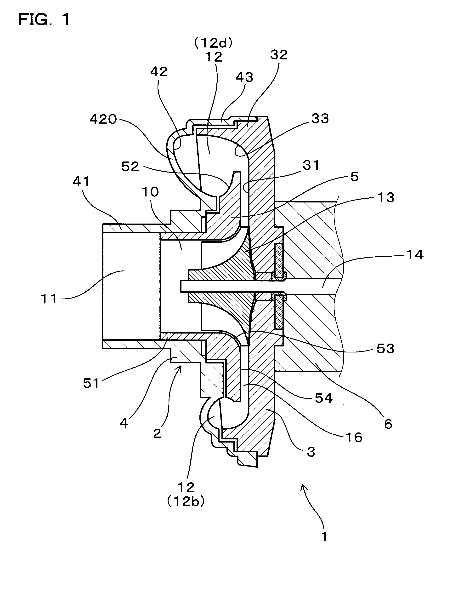
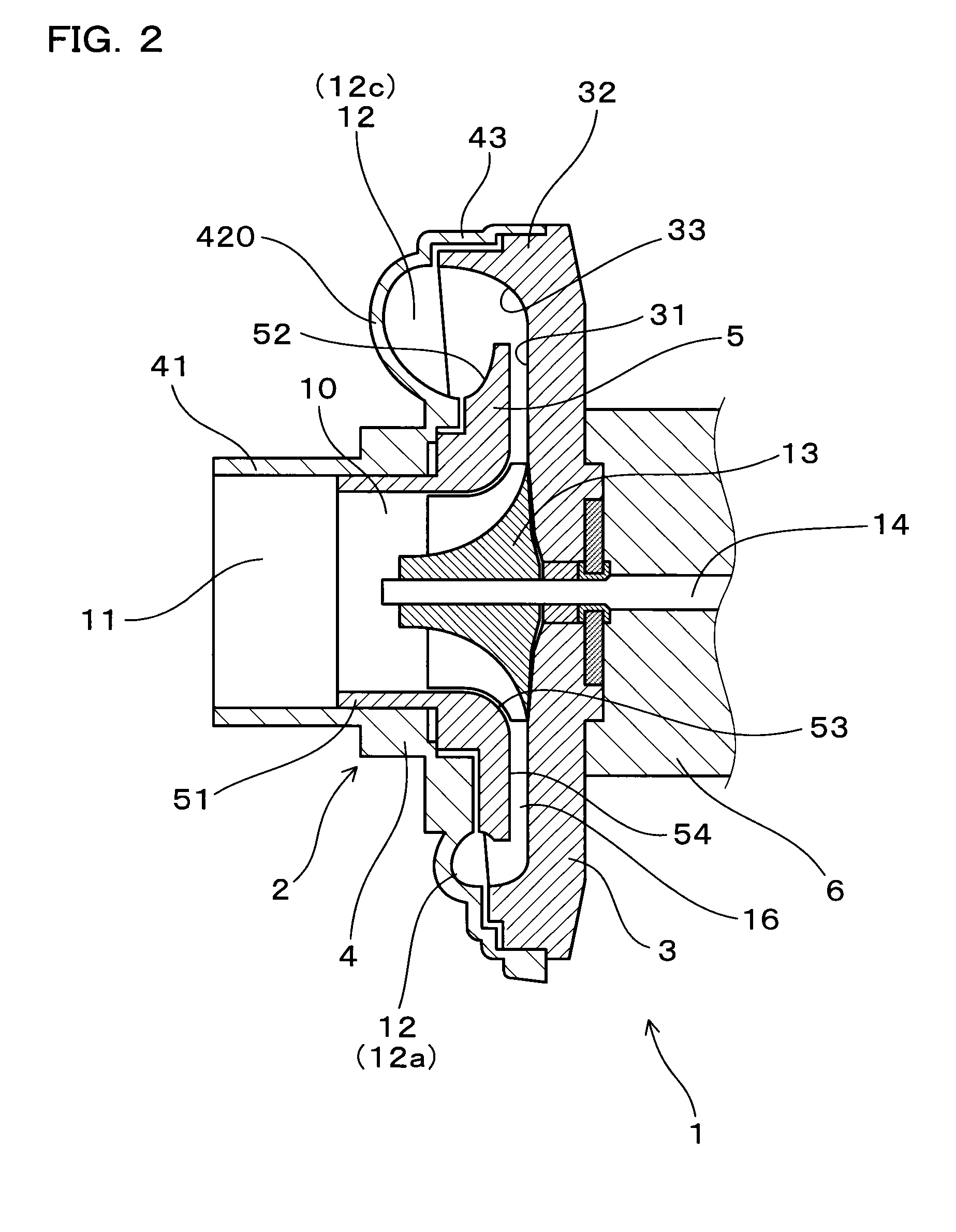
[0050]A first embodiment of the turbocharger and the method of producing thereof will be described with reference to FIGS. 1 to 13.

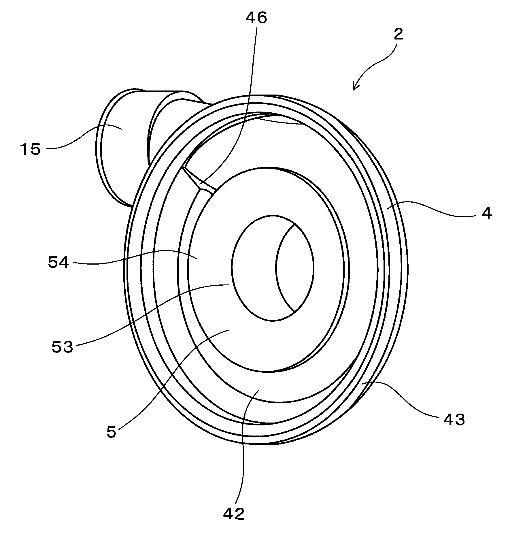
[0051]As shown in FIG. 1, a turbocharger 1 of the first embodiment includes a compressor housing 2 provided therein with an air flow passage 10 in which an impeller 13 is disposed, a bearing housing 6 which rotatably supports a rotor shaft 14 which is connected to the impeller 13, and a back plate 3 which is disposed between the bearing housing 6 and the compressor housing 2 and which faces a part of the air flow passage 10.

[0052]The air flow passage 10 includes a suction port 11 from which air is sucked toward the impeller 13, and a discharge scroll chamber 12 which is formed on an outer peripheral side of the impeller 13 in its circumferential direction, and which guides compressed air discharged from the impeller 13 to a discharge port 15 (see FIG. 3). As shown in FIG. 6, the discharge scroll chamber 12 has such a shape that a cross-sectional area the...


PUM

PropertyMeasurementUnit
shapeaaaaaaaaaa
radius of curvatureaaaaaaaaaa
sizeaaaaaaaaaa

Abstract

A turbocharger includes a compressor housing, a bearing housing and a back plate. A discharge scroll chamber has such a shape that a cross-sectional area thereof gradually increases toward a discharge port in a circumferential direction. The compressor housing includes a scroll piece assembled to a shroud piece. The scroll piece includes a suction port-forming portion, a suction-side concave surface and a scroll outer periphery. The shroud piece includes a shroud fit-in portion, an inner peripheral concave surface, a shroud surface and a diffuser surface. The back plate includes a facing surface, an outer peripheral annular fit-in portion and an outer peripheral concave surface. The outer peripheral concave surface has such a shape that a cross sectional shape thereof formed by a plane including a rotation axis of an impeller gradually changes in the circumferential direction.

Description

CROSS-REFERENCE[0001]This application claims priority to Japanese patent application no. 2012-207890 filed on Sep. 21, 2012, the contents of which are entirely incorporated herein by reference.BACKGROUND OF THE INVENTION[0002]1. Field of the Invention[0003]The present invention relates to a turbocharger in which a back plate is disposed between a compressor housing and a bearing housing, and the invention also relates to a method of producing the turbocharger.[0004]2. Description of the Related Art[0005]A turbocharger installed in a car or the like is configured such that air sucked in a compressor is compressed and discharged toward an internal combustion engine. That is, a discharge scroll chamber into which compressed air discharged from an impeller flows is formed in an air flow passage formed inside of a compressor housing, the discharge scroll chamber guides compressed air into a discharge port, and the compressed air from the discharge port is discharged toward the internal c...

Claims


Application Information

Patent Timeline
Patent Type & Authority Applications(United States)
IPC IPC(8): F04D29/52
CPCF04D29/522F04D25/024F04D29/4206F04D29/624F01D9/026F01D25/24F05D2220/40F05D2230/21F05D2230/51F05D2260/36Y10T29/4924
Inventor ISOGAI, TOMOYUKI
Owner OTICS CORP
Why Eureka
Try Eureka