Femtosescond laser system for the exact manipulation of material and tissues

a laser system and tissue technology, applied in the field of tissue exact manipulation, can solve the problems of unsuitable industrial or medical use, unsatisfactory use of laser source, and unsuitable use of laser source, and achieve the effect of elegant production, high machining precision, and reduced thermal and mechanical stresses on non-machined areas

Active Publication Date: 2014-03-27
CARL ZEISS MEDITEC AG
View PDF11 Cites 5 Cited by
  • Summary
  • Abstract
  • Description
  • Claims
  • Application Information

AI Technical Summary

Benefits of technology

[0013]The means for beam formation and / or beam deflection or, in more general terms, the beam-formation and deflection systems, can include diffractive or refractive microlens systems or adaptive lens systems or standard optical systems. Several standard or conventional optical elements can be replaced by diffractive or refractive elements. When using such a relatively costly beam-formation and deflection system, relatively simple lasers can be used.
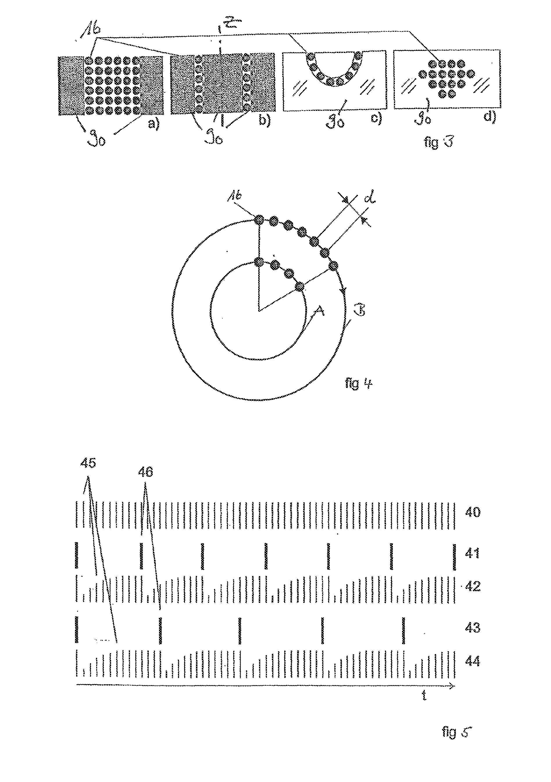
[0038]In the case of a preferred embodiment of the invention, a device is provided with which the pulsed working beam can be applied to the material by the beam-deflection apparatus and during which the repetition rate of the pulses of the working beam can be modified. By providing an apparatus for modifying the repetition rate while simultaneously guiding the beam of the working beam over the material to be machined, in this way a regular spot pattern can be elegantly produced on the material to be treated, even if the beam is directed onto the material to be machined at different angles or at different speeds by the deflection apparatus. A particularly striking advantage is achieved for example if the deflection apparatus deflects the beam in orbits onto the material to be machined and these orbits are produced with a special rotational frequency of the deflection apparatus, in particular for example the deflection mirrors. If, at a rotational frequency of for example 50 Hz, the laser beam is guided on an orbit of 1 cm diameter at a repetition rate of 300 kHz, 60,000 spots are placed uniformly distributed on each orbit per rotation. If the beam is then guided on a circle of only 0.5 cm in diameter with the same frequency of the deflection apparatus, the same distance between the individual spots on the material to be machined can be produced by reducing the repetition rate of the pulsed working beam as when guiding the beam on the larger orbit. Through a corresponding modification of the repetition rate in relation to the geometry traveled by the deflection apparatus, any desired geometric patterns can be produced on the material to be machined with an essentially constant spot distance. For example, spirals can be traveled with which, while the rotational frequency of the deflection apparatus remains constant, the repetition rate constantly decreases from the outside in. In addition, any other desired geometric shapes are conceivable. If it is not actually intended to maintain a constant distance between the individual spots on the material, but rather to achieve a higher spot density in a specific area and a lower spot density in another area, this can likewise be produced by combining the chosen parameters for the repetition rate of the working beam and the frequency or the local course of the deflection apparatus. Thus it is preferably also possible to produce gradually differing areas with a different focus density. For example, with a circle, the center can have a very low focal distance whilst the focal distance from the edge becomes ever greater.

Problems solved by technology

While these laser sources are suitable for uses with high ablation rates per laser pulse, they are not ideal for the use described above for precision cuts.
However, as a single laser pulse does not lead to the formation of a cavitation bubble, but several pulses positioned at the same point are necessary to achieve a cutting action, this method is suitable only for very fine cut figures on a micrometer scale.
This laser source is not suitable for industrial or medical use.

Method used


Image

  • Femtosescond laser system for the exact manipulation of material and tissues
  • Femtosescond laser system for the exact manipulation of material and tissues
  • Femtosescond laser system for the exact manipulation of material and tissues

Examples


Embodiment Construction

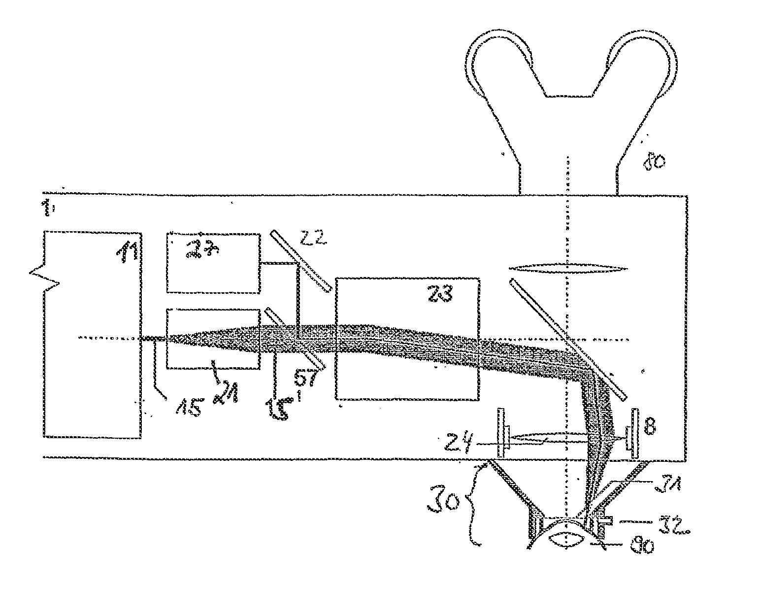
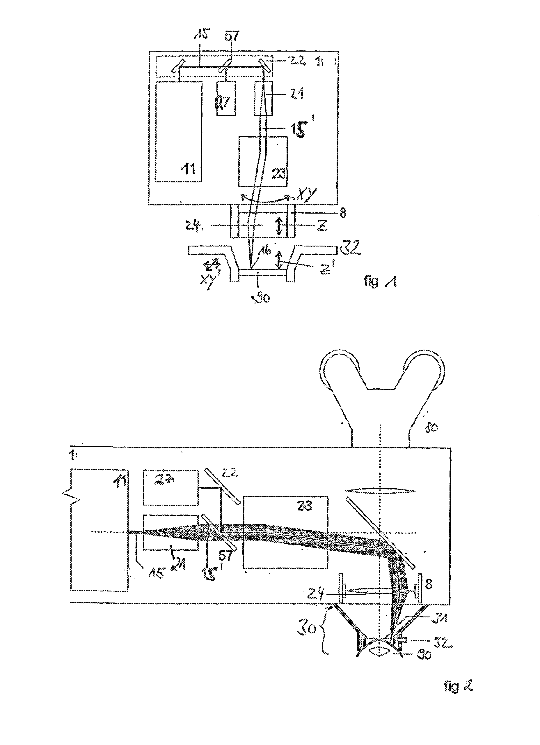
[0049]FIG. 1 is a schematic representation of the individual components of an embodiment of a laser system according to the invention. The machining device 1 includes a cavity-dumped fs oscillator as beam source 11. The laser beam 15 is decoupled via mirrors and a beam splitter 57 onto a beam-expansion lens system 21. The expanded laser beam 15′ is then deflected in XY direction onto a beam-focusing apparatus 24 via a beam-deflection apparatus, such as for example a scanner. This is displaceable in the Z axis and thus allows the displacement of the focus point by displacement of the beam-focusing apparatus along the arrow Z. Alternatively, a focusing optical system with adjustable focal length can be used in order to displace the focus position in Z direction in controlled manner. The focused laser spot 16 is thus steered onto the material 90 to be machined which is held in position by a fixing device 32. Here, the material 90 is a contact lens to be machined. The spot 16 can also b...


PUM

PropertyMeasurementUnit
pulse energyaaaaaaaaaa
energyaaaaaaaaaa

Abstract

A device for the exact manipulation of material, especially of organic material, includes a pulsed laser system with a radiation source, said radiation source being a cavity-dumped fs oscillator.

Description

[0001]This application is a continuation of U.S. patent application Ser. No. 10 / 501,679, the entire disclosure of which is incorporated by reference herein.[0002]The invention relates to a femtosecond laser system for the precise machining of material and tissue, in particular a laser apparatus for the precise, micrometer-accurate machining of organic material, preferably an eye.BACKGROUND[0003]In a valuable contribution to the state of the art it is described in the applicant's patent specification DE 197 46 483 how macroscopic quantities of material are ablated, evaporated or melted with micrometer precision in the machining of extensive areas of materials with lasers with a large spot diameter (mm cm) (CO2 lasers, Nd:YAG, excimers, etc.).[0004]In a further valuable contribution to the state of the art, there is described in the applicant's patent specification DE 197 27 573 an algorithm as to how a laser beam can be deflected to ensure the best possible and precise machining of m...

Claims


Application Information

Patent Timeline
Patent Type & Authority Applications(United States)
IPC IPC(8): A61F9/008A61F9/009B23K26/06B23K26/00B23K26/04A61B18/20A61F9/007B23K26/0622B23K26/082H01S3/00
CPCA61F9/008B23K26/0027A61F9/009B23K26/06B23K26/04B23K26/08H01S3/10046H01S3/1103A61F9/00827A61F9/00831A61F9/00836A61F9/0084A61F2009/00844A61F2009/00865A61F2009/00868A61F2009/0087A61F2009/00872A61F2009/00874A61F2009/00895B23K26/0006B23K26/082B23K26/0624B23K2103/32
Inventor BERGT, MICHAELDICK, MANFRED
Owner CARL ZEISS MEDITEC AG
Why Eureka
Try Eureka