Femtosecond laser system for the exact manipulation of material and tissues

a laser system and tissue technology, applied in the field of tissue exact manipulation laser system, can solve the problems of unsuitable industrial or medical use, unsatisfactory use of laser source, and unsuitable use of laser source, and achieve the effect of elegant production, high machining precision, and reduced thermal and mechanical stresses on non-machined areas

Active Publication Date: 2013-11-19
CARL ZEISS MEDITEC AG
View PDF35 Cites 15 Cited by
  • Summary
  • Abstract
  • Description
  • Claims
  • Application Information

AI Technical Summary

Benefits of technology

[0035]With these repetition rates, the laser action for the photodisruption can be precisely localized in tune with the preset pulse energy and the deflection apparatuses. The material structure is thereby destroyed in a sharply limited focus volume, while in general there is no change in the material in closely adjacent areas (less than a micrometer away). This results in a high machining precision (micrometer accuracy) while sparing adjacent material areas. Thermal and mechanical stresses on the non-machined areas are much lower than with other machining methods.
[0036]In the case of a further preferred version of the device according to the invention, a working beam of the beam source can be applied by the beam apparatus, in particular the deflection apparatus, in geometrically predeterminable form in a temporally predeterminable pattern to the material. Through the co-operation of the individual components, it is thus possible to produce cuts and structures. To produce a spot in which the material structure has been dissolved, a laser pulse with defined pulse parameters (pulse energy, pulse duration, focus) is generally sufficient. For cuts and structures, a large number of such spots are to be placed close alongside one another. The distance between adjacent spots should be of the order of the spot diameter at the end of the procedure. For this, the laser focus can be moved scanning over or through the material. The laser focus ideally follows a preset geometric path in 3 dimensions with micrometer precision. Thus it is possible for example to produce a cut in the material to be machined in that one desired surface after another in the tissue, for example a rectangular surface of adjacent micrometer spots, is triggered to be scanned. As a result the material cohesion is dissolved precisely in this plane and a “cut” in the tissue produced as a result. It is equally possible to apply the laser focus to the material to be machined through circular movements of the scanner in an orbit. Through a subsequent helical guiding of the working beam, a cylinder surface can thus for example be cut out of the material. As the photodisruption preferably takes place in a very narrow area, the laser beam can also act in the tissue without the material penetrated by the laser beam outside the focus being damaged. In this way, any desired geometric paths, and thus shapes, can be cut out in the material by photodisruption.
[0037]In the case of a preferred embodiment of the invention, a device is...

Problems solved by technology

While these laser sources are suitable for uses with high ablation rates per laser pulse, they are not ideal for the use described above for precision cuts.
However, as a single laser pulse does not lead to the formation of a cavitation...

Method used


Image

  • Femtosecond laser system for the exact manipulation of material and tissues
  • Femtosecond laser system for the exact manipulation of material and tissues
  • Femtosecond laser system for the exact manipulation of material and tissues

Examples


Embodiment Construction

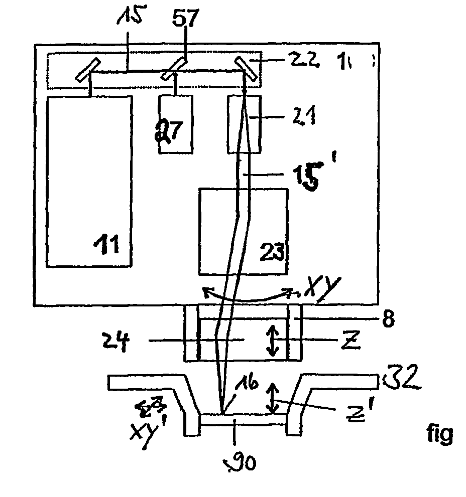
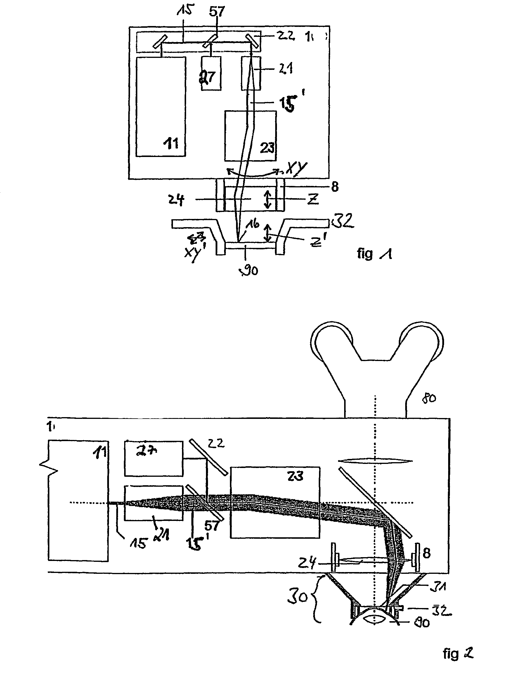
[0047]FIG. 1 is a schematic representation of the individual components of an embodiment of a laser system according to the invention. The machining device 1 includes a cavity-dumped fs oscillator as beam source 11. The laser beam 15 is decoupled via mirrors and a beam splitter 57 onto a beam-expansion lens system 21. The expanded laser beam 15′ is then deflected in XY direction onto a beam-focusing apparatus 24 via a beam-deflection apparatus, such as for example a scanner. This is displaceable in the Z axis and thus allows the displacement of the focus point by displacement of the beam-focusing apparatus along the arrow Z. Alternatively, a focusing optical system with adjustable focal length can be used in order to displace the focus position in Z direction in controlled manner. The focused laser spot 16 is thus steered onto the material 90 to be machined which is held in position by a fixing device 32. Here, the material 90 is a contact lens to be machined. The spot 16 can also b...


PUM

PropertyMeasurementUnit
Timeaaaaaaaaaa
Timeaaaaaaaaaa
Timeaaaaaaaaaa

Abstract

A a device for the exact manipulation of material, especially of organic material. includes a pulsed laser system with a radiation source, said radiation source being a cavity-dumped fs oscillator.

Description

[0001]The invention relates to a femtosecond laser system for the precise machining of material and tissue, in particular a laser apparatus for the precise, micrometer-accurate machining of organic material, preferably an eye.BACKGROUND[0002]In a valuable contribution to the state of the art it is described in the applicant's patent specification DE 197 46 483 how macroscopic quantities of material are ablated, evaporated or melted with micrometer precision in the machining of extensive areas of materials with lasers with a large spot diameter (mm-cm) (CO2 lasers, Nd:YAG, excimers, etc.).[0003]In a further valuable contribution to the state of the art, there is described in the applicant's patent specification DE 197 27 573 an algorithm as to how a laser beam can be deflected to ensure the best possible and precise machining of material.[0004]In U.S. Pat. No. 5,656,186, a method for machining material while simultaneously avoiding or minimizing harmful side effects (melt edges, ther...

Claims


Application Information

Patent Timeline
IPC IPC(8): A61B18/20A61F9/007B23K26/0622B23K26/082H01S3/00
CPCB23K26/0635B23K26/06B23K26/0807A61F9/00827A61F9/00831A61F9/00836A61F9/0084A61F9/009A61F9/008B23K26/0027B23K26/04B23K26/08H01S3/10046H01S3/1103A61F2009/00844A61F2009/00865A61F2009/00868A61F2009/0087A61F2009/00872A61F2009/00874A61F2009/00895B23K26/0006B23K26/082B23K26/0624B23K2103/32
Inventor BERGT, MICHAELDICK, MANFRED
Owner CARL ZEISS MEDITEC AG
Why Eureka
Try Eureka