Cardiac valve prosthesis deployment system
- Summary
- Abstract
- Description
- Claims
- Application Information
AI Technical Summary
Benefits of technology
Problems solved by technology
Method used
Image
Examples
Embodiment Construction
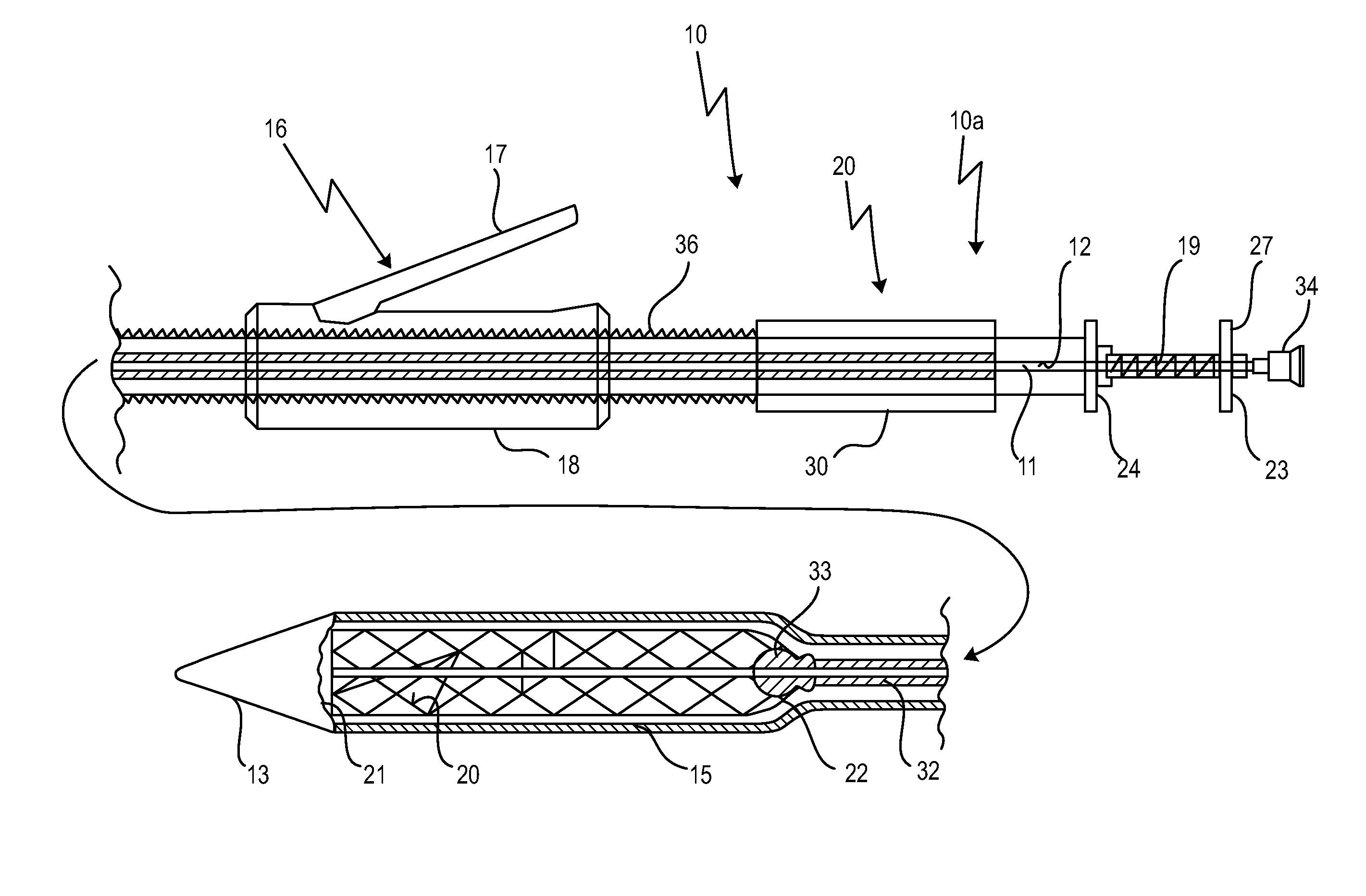
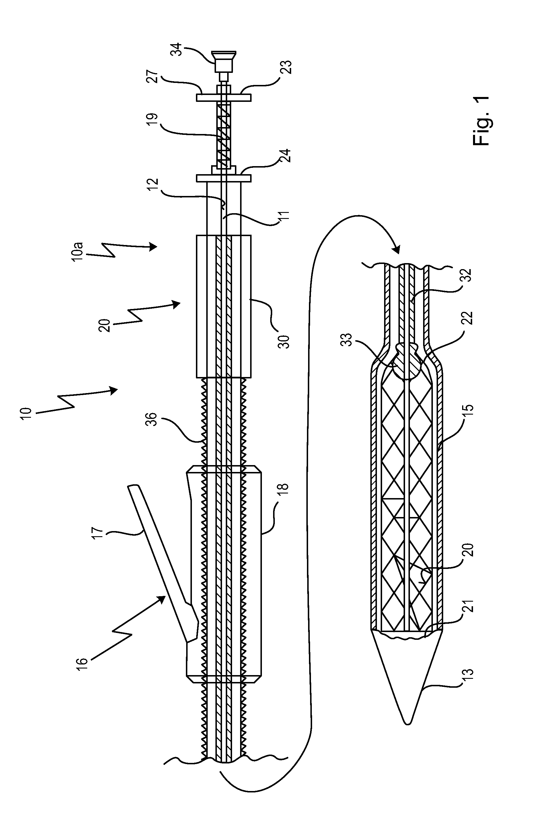
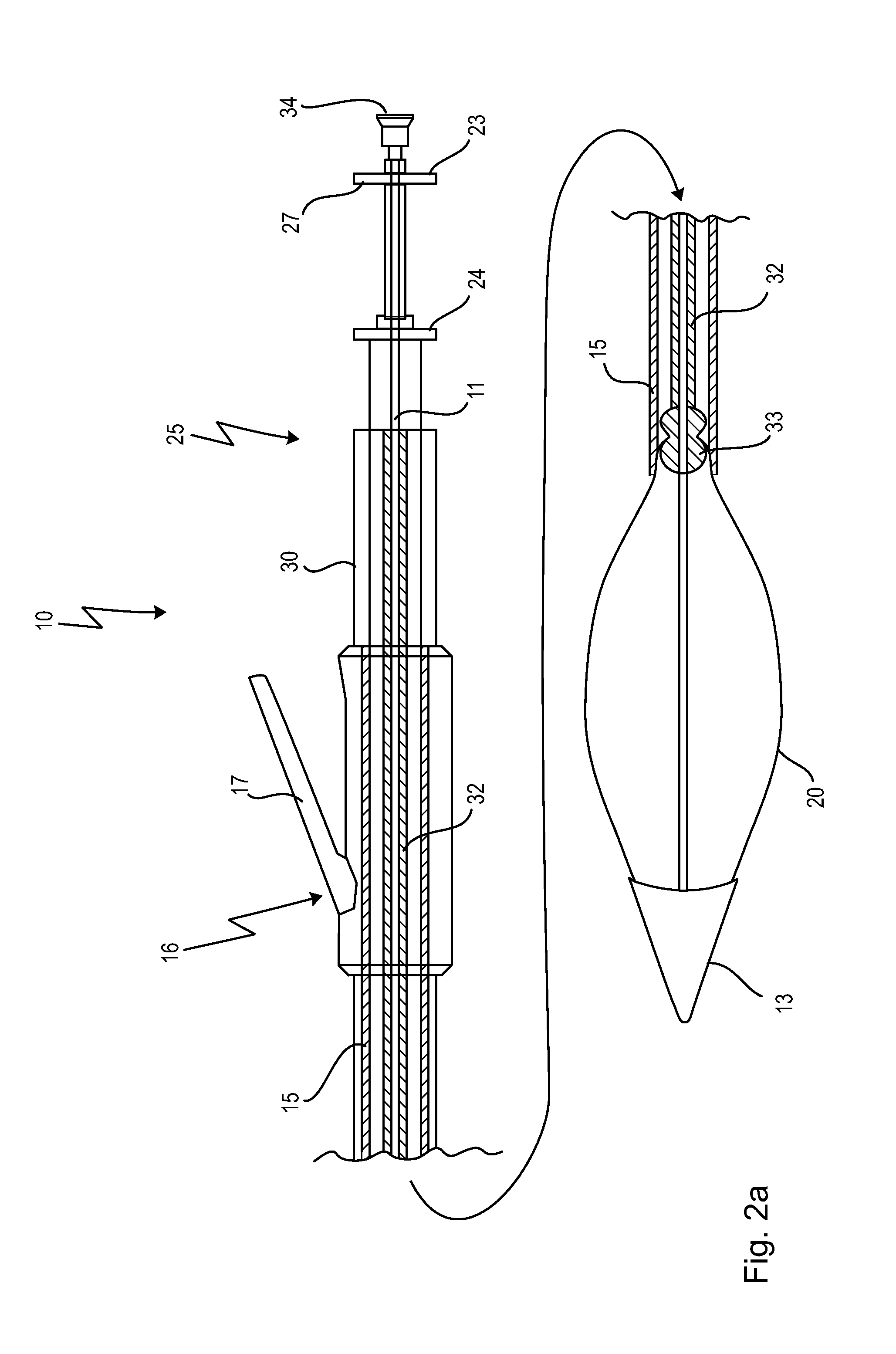
[0071]In FIG. 1, an embodiment of the deployment system according to the invention is generally designated with 10. The deployment system 10, not drawn to scale and showing a proximal portion 10a and a distal portion 10b of the deployment system, comprises a first tube 11, having a lumen 12 designed for accommodating a guidewire (not shown). In FIG. 1, the deployment system 10 has loaded thereupon a prosthesis 20, which is carried by and loaded onto a distal portion 11a of the tube 11. The tube 11 has, on its very distal end, a tip 13 representing an atraumatic tip, having, on its side facing towards the proximal direction, means for accommodating and detachably holding a proximal end 21 of the prosthesis 20.
[0072]The deployment system 10 further comprises an outer sheath 15, holding and compressing the prosthesis 20 in its compressed state when loaded on the first tube 11. The outer sheath 15 is slidable / retractable in proximal direction, i.e. towards the operator, in order release...
PUM
 Abstract
Description
Claims
Application Information
 - R&D
- Intellectual Property
- Life Sciences
- Materials
- Tech Scout
- Unparalleled Data Quality
- Higher Quality Content
- 60% Fewer Hallucinations
Browse by: Latest US Patents, China's latest patents, Technical Efficacy Thesaurus, Application Domain, Technology Topic, Popular Technical Reports.
© 2025 PatSnap. All rights reserved.Legal|Privacy policy|Modern Slavery Act Transparency Statement|Sitemap|About US| Contact US: help@patsnap.com


