Generator

a generator and power technology, applied in the direction of machines/engines, couplings, fluid couplings, etc., can solve the problems of large stiig and yeh concepts, high cost, and general unsuitability for general commercial units, and achieve the effect of increasing power generation efficiency

Inactive Publication Date: 2014-04-03
AKBAR AHSAN
View PDF5 Cites 13 Cited by
  • Summary
  • Abstract
  • Description
  • Claims
  • Application Information

AI Technical Summary

Benefits of technology

[0030]Another advantage of the invention is that it provides a power generator that is mobile and may be used with various transportation systems.
[0031]A further advantage of the invention is that it provides a power generator that exploits the vortex properties of air to increase power generation efficiency.
[0032]Additional objects, advantages and novel features of the examples will be set forth in part in th

Problems solved by technology

In total the Stiig and Yeh concepts are quite huge, complex, expe

Method used


Image

  • Generator
  • Generator
  • Generator

Examples


Embodiment Construction

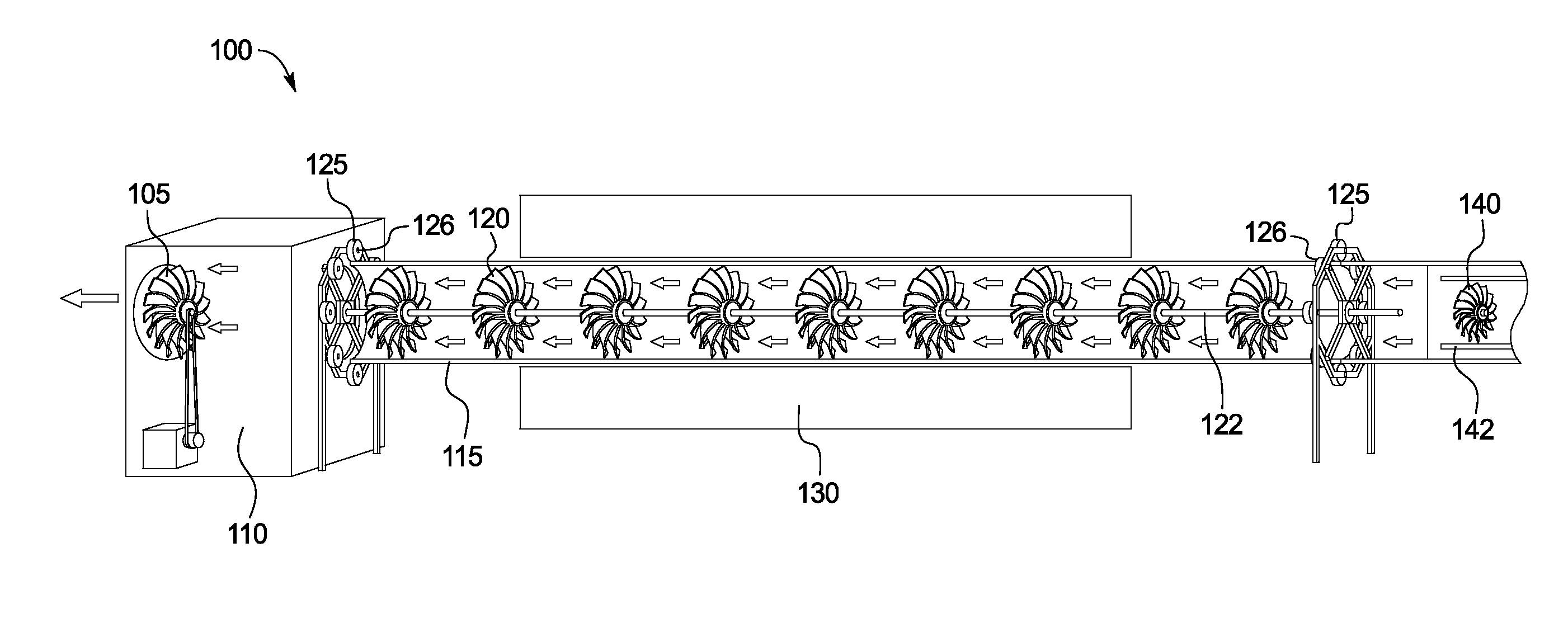
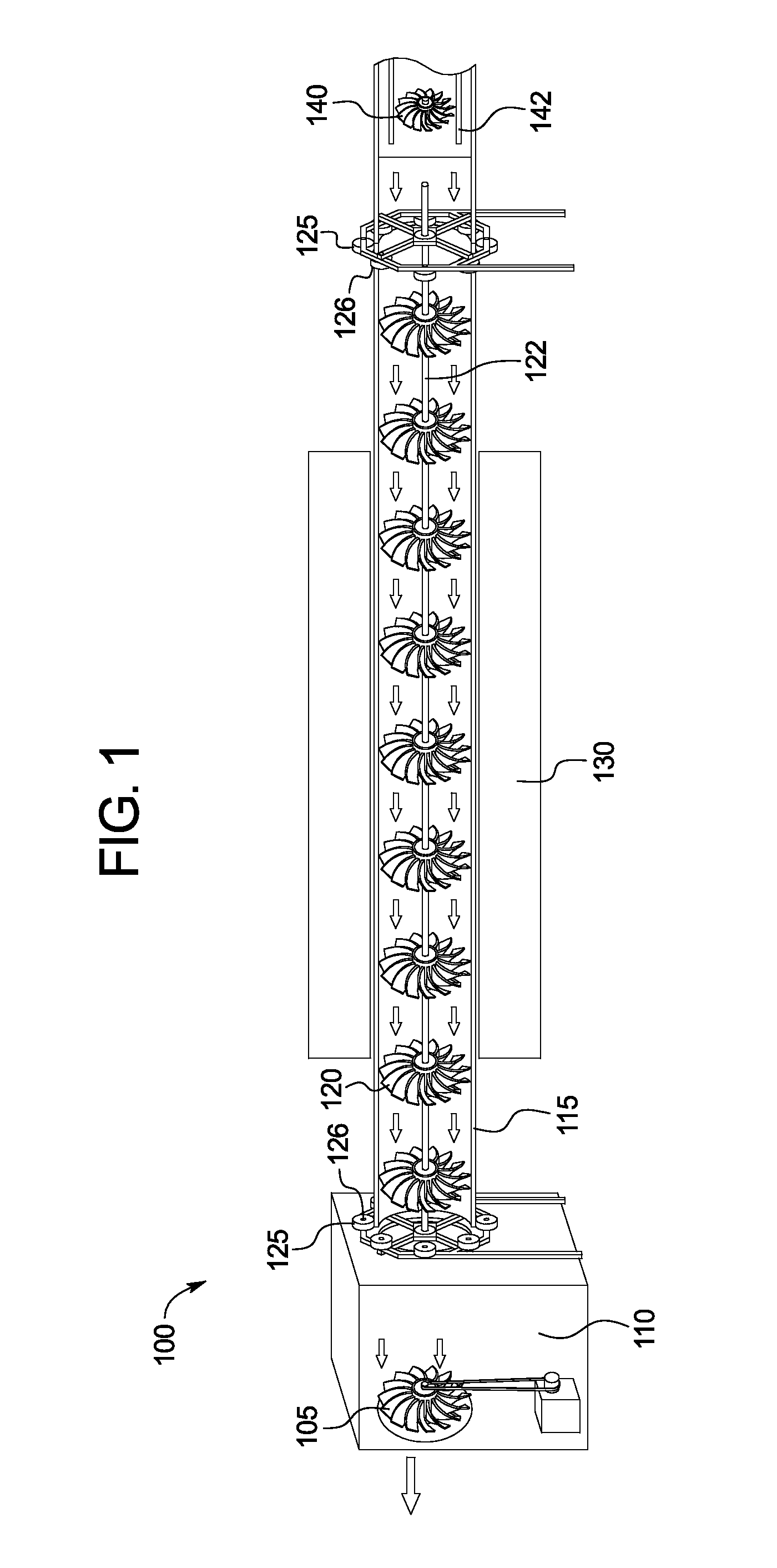
[0043]FIG. 1 illustrates a schematic side view of an example of a generator 100 according to the presently disclosed subject matter. It is understood that there are numerous ways to implement the generator 100 to accomplish the advantages disclosed herein and the following examples are provided for illustrative purposes of the disclosed solutions.

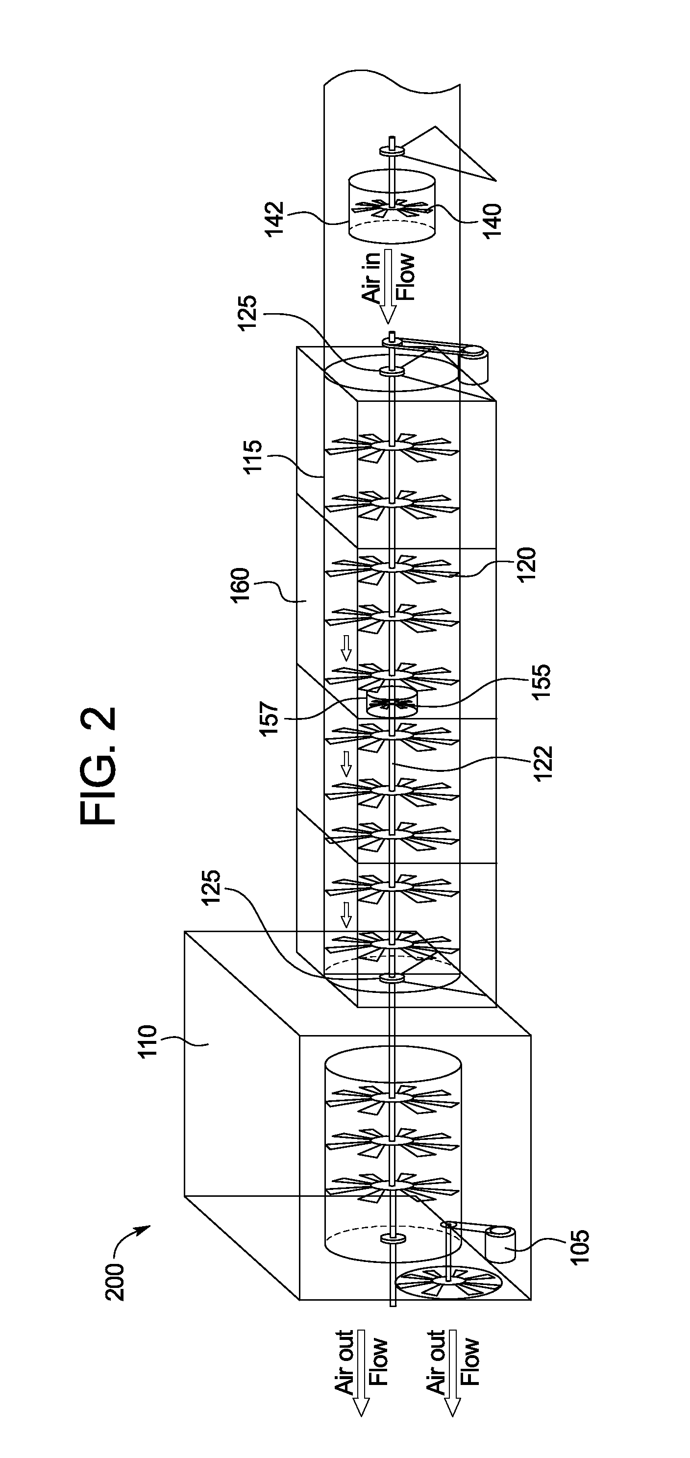
[0044]As shown in FIG. 1, the example of the generator 100 shown includes an exhaust fan 105 adapted to draw a partial vacuum in a chamber 110. After a partial vacuum is drawn within the chamber 110, air may flow into the generator 100 through a rotating turbine pipe 115, which forms the rotational element of an electro-magnetic generator. Rotation of the turbine pipe 115 is caused by the airflow through the turbine pipe 115 interacting with a series of turbine blades 120 located within the turbine pipe 115. The inflowing air is drawn across the turbine blades 120 creating a whirling mass of airflow, which causes the rotation of the turbine...


PUM


Abstract

A generator includes: a housing defining a chamber; a fan in fluid communication with the chamber, wherein the fan is oriented to draw a partial vacuum in the chamber; a pipe including a first opening and a second opening, wherein the first opening is in fluid communication with the chamber and the second opening is in fluid communication with the ambient atmosphere, such that when a partial vacuum is drawn in the chamber a partial vacuum is drawn within the pipe; a plurality of turbine blades within the pipe configured such that airflow from the second opening towards the first opening flows across the plurality of turbine blades to cause the turbine blades to rotate; a rotating element driven into rotational movement by the rotation of the turbine blades; and an electro-magnetic generator configured such that the rotating pipe is a rotating element within the electro-magnetic generator.

Description

CROSS-REFERENCE TO RELATED APPLICATIONS[0001]This application claims the benefit of U.S. Provisional Application No. 61 / 708,053, filed on Oct. 1, 2012, U.S. Provisional Application No. 61 / 718,004, filed on Oct. 24, 2012, U.S. Provisional Application No. 61 / 759,272, filed on Jan. 1, 2013, U.S. Provisional Application No. 61 / 764,399, filed on Feb. 13, 2013, and U.S. Provisional Application No. 61 / 868,857, filed on Aug. 22, 2013, the entirety of each is incorporated herein by reference.TECHNICAL FIELD OF THE INVENTION[0002]The present invention relates to the general field of power generating systems and more particularly to an air driven apparatus that develops a power generator using an artificially created confined vortex or whirling mass of air in the form of a rotating column. More specifically the invention relates to a system and method of developing energy from a source of airflow. In part, the system includes a powerful fan that removes air from the system. The air that is rem...

Claims


Application Information

Patent Timeline
IPC IPC(8): F03D9/00
CPCF03D9/002B60K16/00F05B2240/931F05B2240/941F03D9/25Y02E10/72F03D1/025F03D1/04F03D9/32
Inventor AKBAR, AHSAN
Owner AKBAR AHSAN
Why Eureka
Try Eureka