
Organic light emitting display and method of erasing afterimage thereof

a technology of light emitting display and afterimage, which is applied in the field of erasing an image sticking of an organic light emitting display, can solve the problems of image sticking and image sticking, and achieve the effect of preventing an image sticking

Active Publication Date: 2014-04-03
LG DISPLAY CO LTD
View PDF8 Cites 49 Cited by
  • Summary
  • Abstract
  • Description
  • Claims
  • Application Information

AI Technical Summary

Benefits of technology

The present invention provides an organic light emitting display that can stop showing pictures when it is turned off. This invention also describes a way to erase these pictures if they become stuck.

Problems solved by technology

An organic light emitting diode display may have an image sticking after power-off, and the image sticking may last for a long time.
This image sticking problem occurs because the organic light emitting diode display cannot discharge residual charges in pixels upon power-off.

Method used


Image

  • Organic light emitting display and method of erasing afterimage thereof
  • Organic light emitting display and method of erasing afterimage thereof
  • Organic light emitting display and method of erasing afterimage thereof

Examples


first exemplary embodiment

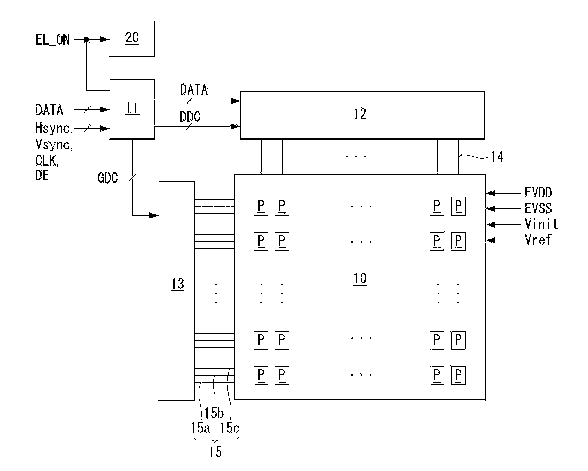
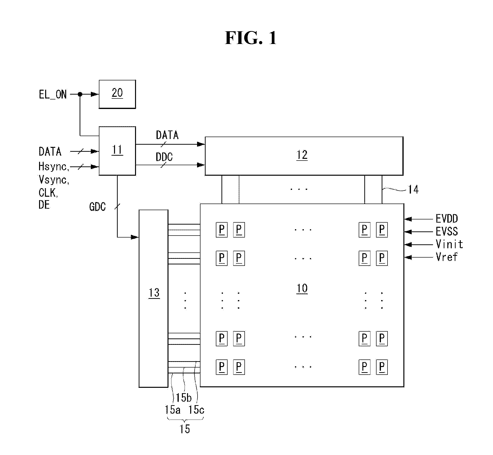
[0034]In the first exemplary embodiment, the timing controller 11 transmits black data to the data driving circuit 12 during at least 1 frame period, and drives the data driving circuit 12 and the gate driving circuit 13 to write the black data to the pixels P. The black data is stored in the timing controller 11 for the purpose of erasing an image sticking in the power-off sequence process, irrespective of input image data. In the timing controller 11, the black data may be set to digital data “000000002” having a black gray scale value and stored in a register. The black data may be set to a dark gray scale, for example, “0000XXXX2”, similar to the black gray scale. Here, X is 0 or 1. The timing controller 11 reads the black data from the register at the start of power-off and transmits it to the data driving circuit 12. In the first exemplary embodiment, the data driving circuit 12 is additionally driven during the power-off delay time Toff to convert the black data input from th...

second exemplary embodiment

[0036]In the second exemplary embodiment, the timing controller 11 may modulate the gate timing control signal GDC to suppress light emission of the pixels P. The gate timing control signal GDC comprises start pulses for indicating the start timing of a scan signal SCAN, an emission control signal EM, and an initialization signal NIT and clock signals for indicating the shift timing of these signals. In the second exemplary embodiment, the timing controller 11 modulates the gate timing control signal GDC to initialize the pixels P and suppress light emission of the pixels P.

[0037]In the second exemplary embodiment, the timing controller 11 supplies no data to the data driving circuit 12. The data driving circuit 12 outputs no data voltage in the power-off sequence process according to the second exemplary embodiment. In the second exemplary embodiment, the gate driving circuit 13 sequentially supplies only signals required to initialize the pixels P under the control of the timing c...


PUM


Abstract

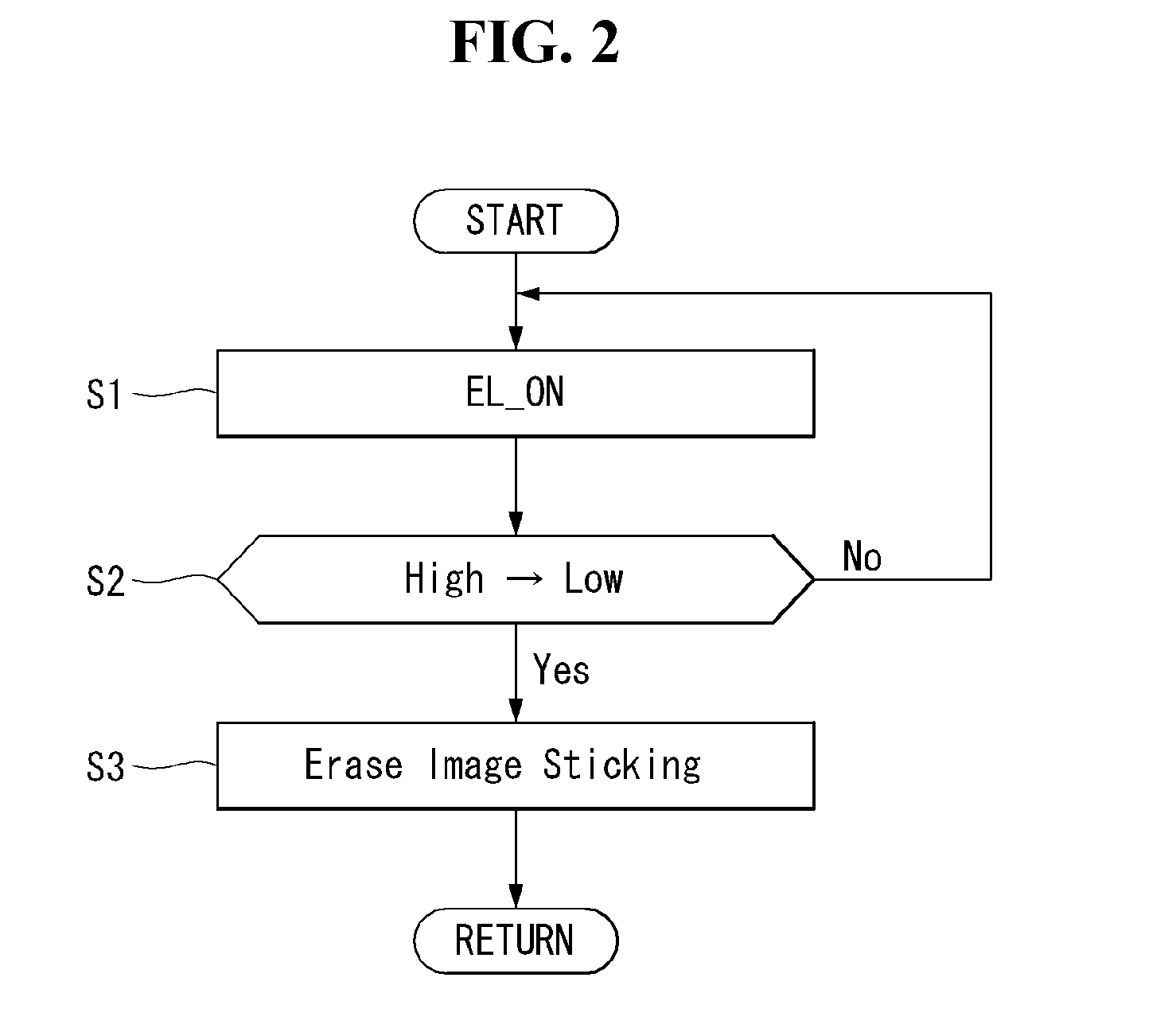
An organic light emitting display and a method of erasing an image sticking thereof are provided. In the image sticking erasing method, a panel driving circuit is driven by a logic power voltage during a power-off delay time to discharge pixels.

Description

[0001]This application claims the benefit of Korean Patent Application No. 10-2012-0108967 filed on Sep. 28, 2012 and Korean Patent Application No. 10-2012-0131463 on Nov. 20, 2012, the entire contents of all these applications are herein by reference for all purposes as if fully set forth herein.BACKGROUND[0002]1. Field[0003]This document relates to an organic light emitting display and a method of erasing an image sticking thereof.[0004]2. Related Art[0005]Pixels of an organic light emitting display each comprises an organic light emitting diode (hereinafter, referred to as “OLED”) which is a self-luminous element. The OLED comprises organic compound layers such as a hole injection layer HIL, a hole transport layer HTL, an emission layer EML, an electron transport layer ETL, and an electron injection layer EIL, which are stacked. The OLED emits light when electrons and holes are combined in an organic layer by allowing current to flow through a fluorescent or phosphorous organic t...

Claims


Application Information

Patent Timeline
Patent Type & Authority Applications(United States)
IPC IPC(8): G09G3/32
CPCG09G3/3291G09G2300/0852G09G2300/0861G09G2310/063G09G2320/0257G09G2330/027G09G3/3233G09G2330/02
Inventor KIM, JOONYOUNGLEE, HYUNKILEE, MUNJUN
Owner LG DISPLAY CO LTD
Learn More