
Liquid crystal display apparatus and alternating current driving method therefore

a technology of liquid crystal display and driving method, which is applied in the direction of instruments, television systems, signal generators with optical-mechanical scanning, etc., can solve the problems of image sticking, adverse effects, image sticking, etc., and achieve the effect of improving display quality and simple configuration

Inactive Publication Date: 2005-10-27
MITSUBISHI ELECTRIC CORP
View PDF9 Cites 7 Cited by
  • Summary
  • Abstract
  • Description
  • Claims
  • Application Information

AI Technical Summary

Benefits of technology

[0017] The invention is accomplished in view of the aforementioned circumstances. Accordingly, the invention provides a liquid crystal display apparatus that improves display quality, and provides an alternating current driving method therefor. More particularly, the invention provides a liquid crystal display apparatus enabled to restrain image sticking from being caused on pixels.
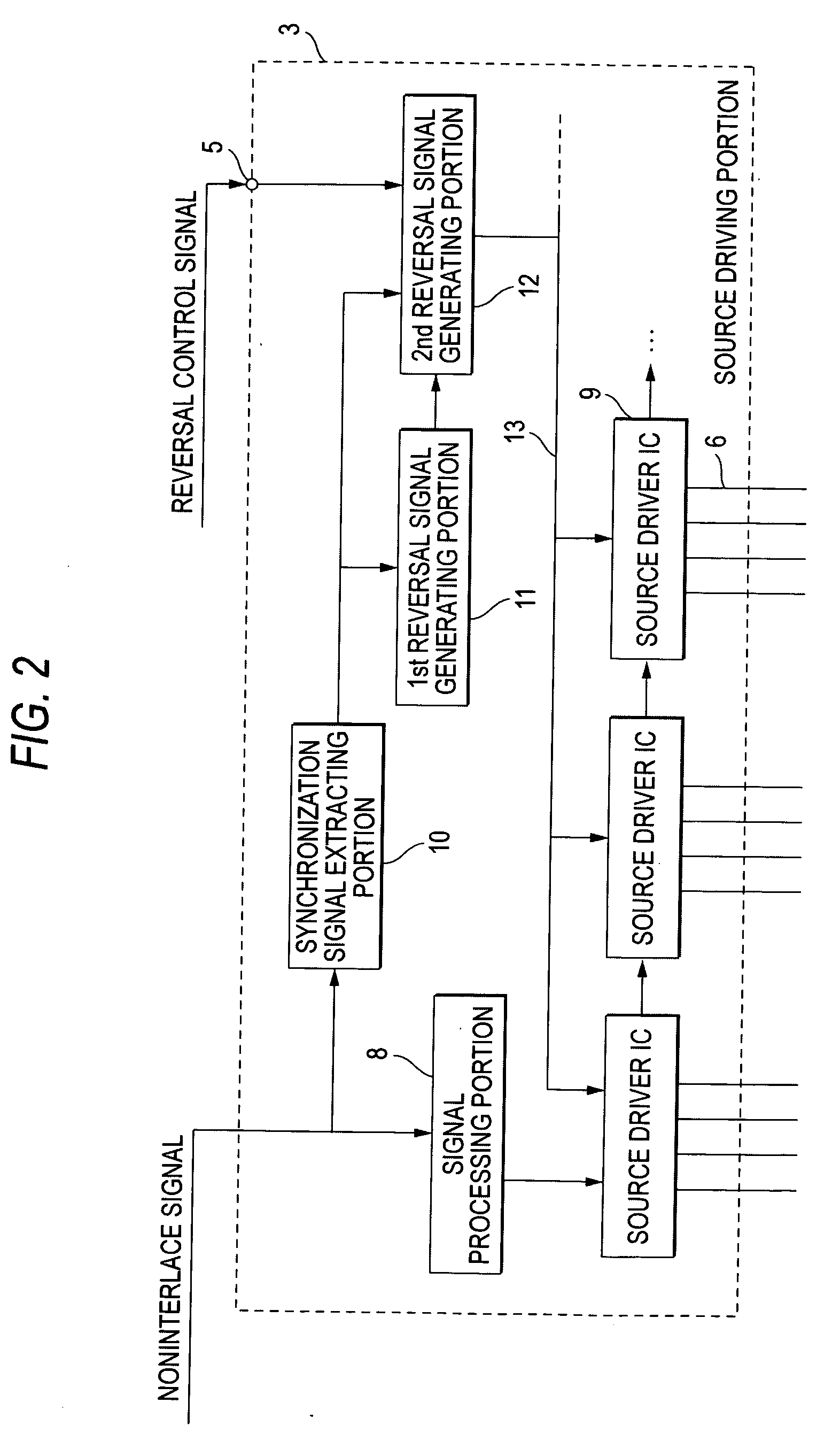
[0019] With such a configuration, the second polarity reversal signal is generated according to the reversal control signal, which is generated according to a result of comparison between the frames. Thus, in a case where a pixel, on which alternating current driving cannot be performed, appears, the polarity of a signal voltage can be reversed according to the reversal control signal. Consequently, the pixel can be restrained from causing image sticking.
[0021] In addition to the configurations, the liquid crystal display apparatus of the invention may have a configuration in which the second reversal signal generating means includes a delay flip-flop circuit and an exclusive-OR circuit, and in which the reversal control signal and the vertical synchronization signal are inputted to the delay flip-flop circuit, and in which an output signal of the delay flip-flop circuit and the first polarity reversal signal are inputted to the exclusive-OR circuit to thereby generate a second polarity reversal signal. With such a configuration, a circuit for restraining image sticking from occurring in a pixel can be realized with a simple configuration.
[0022] According to the liquid crystal display apparatus of the invention and the alternating current driving method of the invention therefor, even in a case where a same image is continuously displayed over plural frames, the polarity of a signal voltage is reversed according to a reversal control signal. Thus, defective indication, such as image sticking of a pixel, can be restrained from occurring. Consequently, the display quality can be improved.

Problems solved by technology

However, the aforementioned conventional liquid crystal display apparatus has a problem in that when showing a noninterlace signal obtained by performing scanning-line interpolation on an interlace signal, a pixel, on which an alternating current driving operation cannot be performed, appears in a case where a same image is continuously shown over plural frames.
When the direct-current component is accumulated therein, each of the pixels causes image sticking.
This has adverse effects.
Thus, it is possible that in a case where such a video signal is inputted, the direct-current component is accumulated in each of the pixels in the display areas to thereby cause image sticking.
As described above, the conventional liquid crystal display apparatus has problems that when a noninterlace signal obtained by performing scanning-line interpolation on an interlace signal is displayed therein, a pixel, in which alternating-current driving cannot be performed, appears in a case where a same image is continuously displayed over plural frames, and that defective indication, such as image sticking, is caused.

Method used


Image

  • Liquid crystal display apparatus and alternating current driving method therefore
  • Liquid crystal display apparatus and alternating current driving method therefore
  • Liquid crystal display apparatus and alternating current driving method therefore

Examples


first embodiment

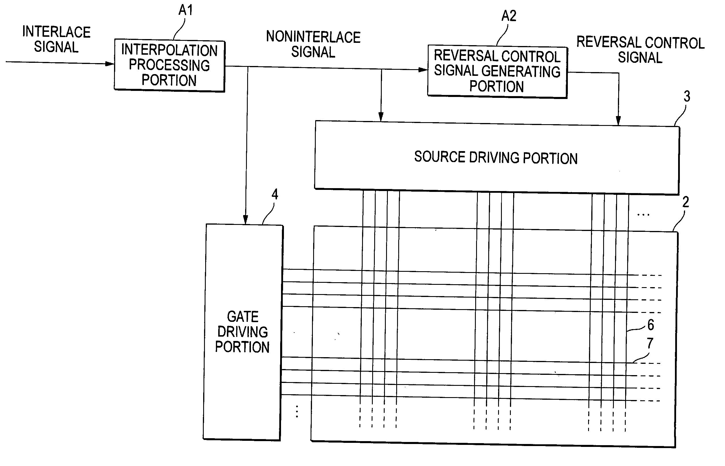
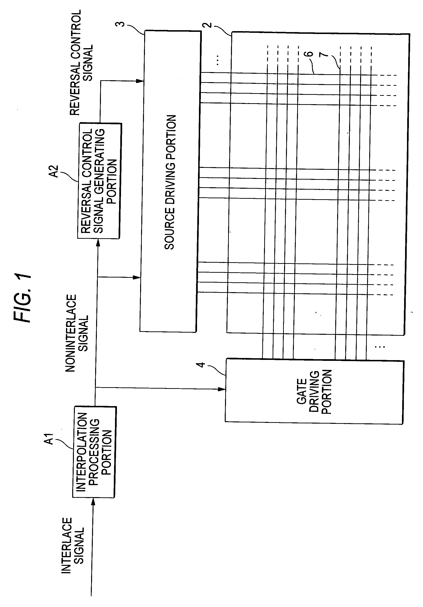
[0036]FIG. 1 is a view showing an example of the rough configuration of a liquid crystal display apparatus according to a first embodiment of the invention. In a liquid crystal apparatus according to this embodiment, an alternating current driving operation is performed according to a reversal control signal. This liquid crystal display apparatus 1 is an active matrix type display apparatus. Each of pixels arranged in a matrix-like manner has a thin film transistor serving as a switching device. This liquid crystal display apparatus 1 includes a liquid crystal display panel portion 2, a source driving portion 3, a gate driving portion 4, an interpolation processing portion A1, and a reversal control signal generating portion A2. An image based on a noninterlace signal, which is obtained by performing scanning line interpolation on an interlace signal, is displayed on the liquid crystal panel portion 2.

[0037] The interpolation processing portion A1 performs interpolation processing ...


PUM


Abstract

A liquid crystal display apparatus includes synchronization signal extracting means for extracting a vertical synchronization signal from a noninterlace signal, first reversal signal generating means for generating a first polarity reversal signal that causes reversal of polarity of a signal voltage every frame for a switching device associated with each of pixels according to the vertical synchronization signal, reversal control signal generating means for generating a reversal control signal according to a result of comparison between frames of the noninterlace signal, second reversal signal generating means for generating a second polarity reversal signal by reversing polarity of the first polarity reversal signal according to the reversal control signal, and switching device driving means for driving each of switching devices according to the second polarity reversal signal.

Description

BACKGROUND OF THE INVENTION [0001] 1. Field of the Invention [0002] The present invention relates to a liquid crystal display apparatus and to an alternating current driving method therefore and, more particularly, to improvement of an alternating current driving type liquid crystal display apparatus adapted to every frame is reverse the polarity of a signal voltage for a switching device, such as a thin film transistor. [0003] 2. Description of the Related Art [0004] It is known that a phenomenon, in which characteristics of a liquid crystal is deteriorated, that is, what is called image sticking occurs in a case where a signal voltage of the same polarity is applied to the same pixel electrode for a long time. Hitherto, to prevent an occurrence of such image sticking, a technique called an “alternating current driving” method, according to which the polarity of a signal voltage written to each pixel is reversed, has been employed. For example, an occurrence of the image sticking i...

Claims


Application Information

Patent Timeline
IPC IPC(8): G02F1/133G09G3/20G09G3/36
CPCG09G3/3614G09G2310/0229G09G2320/0204G09G3/20G09G3/36
Inventor KITAMURA, SACHIOIJIMA, YUKIO
Owner MITSUBISHI ELECTRIC CORP
Learn More