Liquid crystal display device

a liquid crystal display and display device technology, applied in the direction of liquid crystal compositions, instruments, chemistry apparatus and processes, etc., can solve the problems of low direct effect of liquid crystal layer on the liquid crystal layer, low voltage holding ratio, and high impurity control levels of liquid crystal materials constituting such liquid crystal layers, etc., to achieve display defects such as white streaks, increase the ion density, and reduce the voltage holding ratio

Active Publication Date: 2016-08-09
DIC CORPORATION
View PDF46 Cites 7 Cited by
  • Summary
  • Abstract
  • Description
  • Claims
  • Application Information

AI Technical Summary

Benefits of technology

[0021]A liquid crystal display device according to the present invention includes a particular liquid crystal composition and a color filter that contains a particular pigment, so that a decrease in the voltage holding ratio (VHR) and an increase in the ion density (ID) in the liquid crystal layer can be prevented and display defects such as white streaks, variations in alignment, and image sticking can be prevented.

Problems solved by technology

Liquid crystal materials constituting such liquid crystal layers have been subjected to high levels of impurity control since impurities remaining in the materials significantly affect electrical properties of display devices.
However, since an alignment film and a transparent electrode are interposed between the color filter layer and the liquid crystal layer, the direct effects on the liquid crystal layer have been considered to be significantly low compared to those of the alignment film materials.
There is a possibility that impurities contained in the color filter layer may migrate through the alignment film and the transparent electrode and cause a decrease in the voltage holding ratio (VHR) and an increase in the ion density (ID) in the liquid crystal layer, thereby leading to display defects such as white streaks, variations in alignment, and image sticking.
However, these methods do not differ much from simply decreasing the amounts of impurities in the pigment and fail to provide sufficient improvements that resolve the display defects even under the recent progress in pigment purification technologies.
This literature does not resolve the problems related to display defects of liquid crystal display devices that have become increasingly complicated.

Method used


Image

  • Liquid crystal display device
  • Liquid crystal display device
  • Liquid crystal display device

Examples


examples

[0197]Hereinafter, the present invention will be described further in detail with reference to Examples, but the present invention is not limited to these Examples. In compositions of Examples and Comparative Examples below, “%” means “% by mass”.

[0198]In Examples, the measured properties are as follows.

[0199]Tni: nematic phase-isotropic liquid phase transition temperature (° C.)

[0200]Δn: refractive index anisotropy at 25° C.

[0201]Δ∈: dielectric anisotropy at 25° C.

[0202]η: viscosity (mPa·s) at 20° C.

[0203]γ1: rotational viscosity (mPa·s) at 25° C.

[0204]VHR: voltage holding ratio (%) at 70° C.

[0205](a value, which is expressed as a percentage, of the ratio of a measured voltage to an initial applied voltage, the measured voltage being obtained by injecting a liquid crystal composition into a cell having a thickness of 3.5 μm and performing measurement at an application voltage of 5 V, a frame time of 200 ms, and a pulse duration of 64 μs)

[0206]ID: ion density (pC / cm2) at 70° C.

[0207...

examples 1 to 4

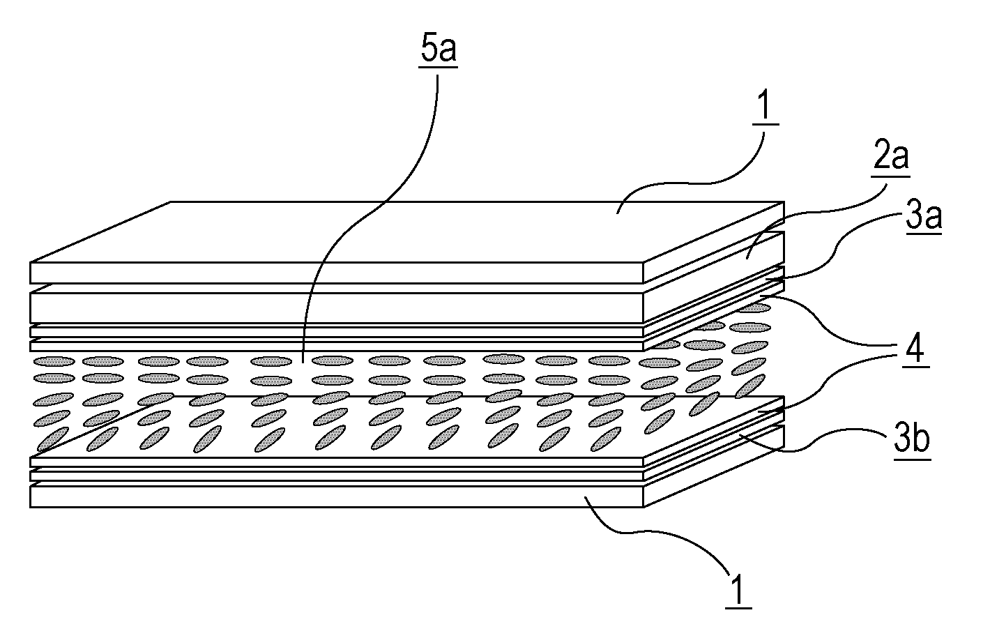
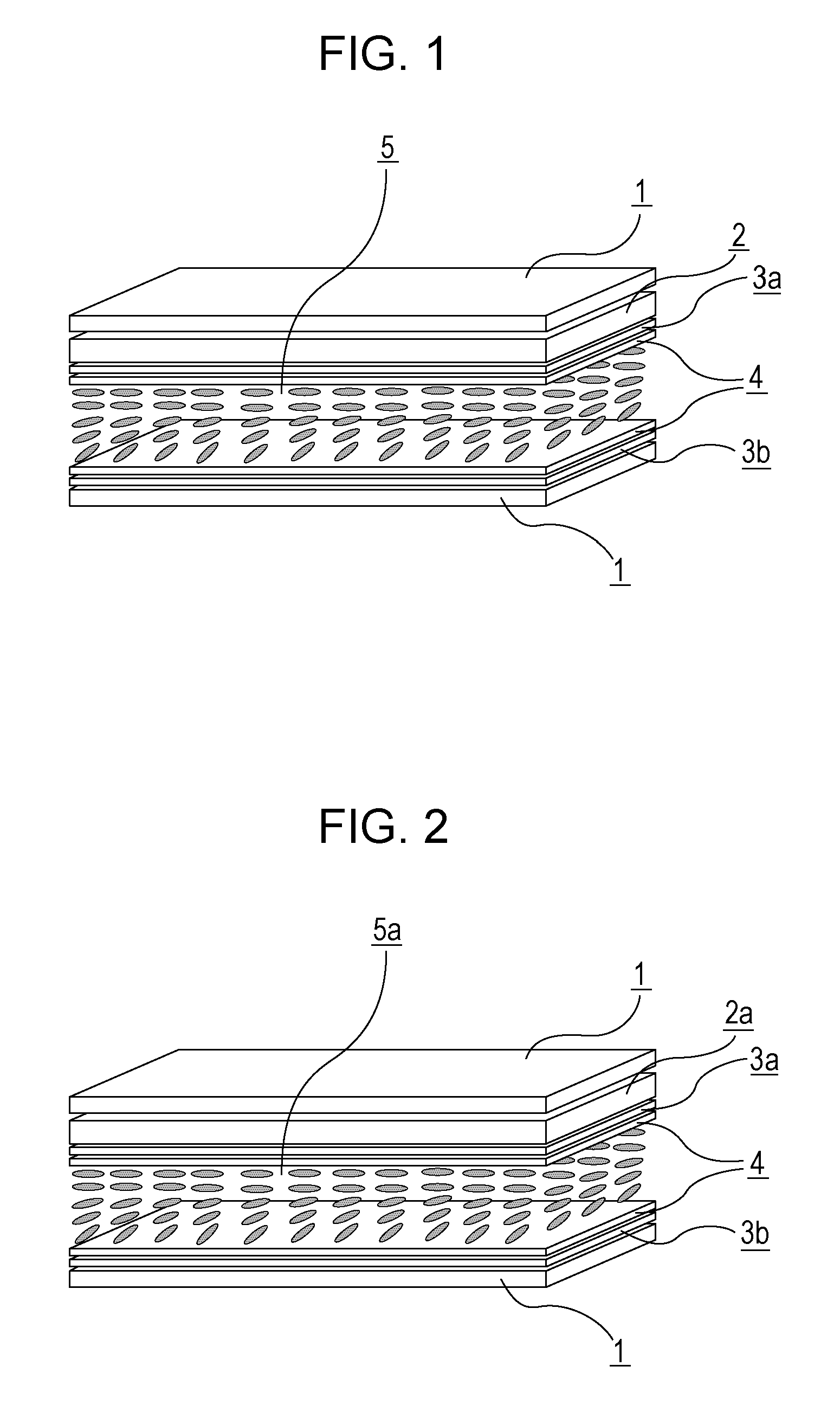
[0244]An electrode structure was formed on at least one of first and second substrates, and an alignment film having a horizontal alignment property was formed on each of surfaces of the first and second substrates facing each other. Then, a weak rubbing treatment was performed, an IPS cell was made, and a liquid crystal composition 1 described below was sandwiched between the first substrate and the second substrate. Table 11 shows the physical properties of the liquid crystal composition 1. Subsequently, liquid crystal display devices of Examples 1 to 4 were produced using the color filters 1 to 4 listed in Table 9 (dgap=4.0 μm, alignment film AL-1051). The VHR and ID of the produced liquid crystal display devices were measured. The image sticking of the produced liquid crystal display devices was also evaluated. Table 12 shows the results.

[0245]

[Chem. 24]Chemical structureProportionAbbreviation48% 3-Cy—Cy-1d04%3-Cy—Cy-1d18%1-Ph—Ph-3d15%3-Cy—Ph—Ph-25%2-Ph—Ph1—Ph-32%3-Ph—Ph3—CFFO—P...

examples 5 to 12

[0250]Liquid crystal compositions 2 and 3 listed in Table 13 were sandwiched as in Example 1. Liquid crystal display devices of Examples 5 to 12 were produced using the color filters listed in Table 9 and the VHR and ID were measured. The image sticking of the liquid crystal display devices was also evaluated. Tables 14 and 15 show the results.

[0251]

TABLE 13Name of compoundContent (%)Liquid crystal composition 24-Cy-Cy-1d0150d1-Cy-Cy-Ph-140d3-Cy-Cy-Ph-1143-Cy-Ph—Ph-Cy-333-Cy-Ph—Ph1-Cy-341-Cy-Cy-Ph3—F92-Cy-Ph—Ph3—F103-Cy-Ph—Ph3—F105-Cy-Ph—Ph3—F50d1-Cy-Cy-Ph1—F83-Cy-Cy-Ph1—Ph3—F82-Ph—Ph3—CFFO—Ph3—F43-Ph—Ph3—CFFO—Ph3—F6Tni / ° C.100.7Δn0.094Δε8.0γ1 / mPa · s108η / mPa · s22.2Liquid crystal composition 35-Cy-Cy-1d053-Cy-Cy-1d1100d1-Cy-Cy-Ph-185-Cy-Cy-Ph—O162-Ph—Ph1—Ph-382-Cy-Cy-Ph3—F113-Cy-Cy-Ph3—F155-Cy-Cy-Ph3—F53-Cy-Ph—Ph3—F63-Cy-Ph—Ph1—F94-Cy-Cy-Ph—OCFFF43-Cy-Cy-CFFO—Ph3—F75-Cy-Cy-CFFO—Ph3—F43-Cy-Cy-Ph1—Ph3—F2Tni / ° C.103.2Δn0.102Δε7.1γ1 / mPa · s96η / mPa · s20.8

[0252]

TABLE 14Example 5Example ...


PUM

PropertyMeasurementUnit
particle sizeaaaaaaaaaa
thicknessaaaaaaaaaa
thicknessaaaaaaaaaa

Abstract

The present invention provides a liquid crystal display device that prevents a decrease in the voltage holding ratio (VHR) and an increase in the ion density (ID) in the liquid crystal layer, and resolves the problems of display defects, such as white streaks, variations in alignment, and image sticking. Since a liquid crystal display device according to the present invention has a feature of preventing a decrease in the voltage holding ratio (VHR) and an increase in the ion density (ID) in the liquid crystal layer, and suppressing the occurrence of display defects such as image sticking, the liquid crystal display device is particularly useful for active matrix driving liquid crystal display devices with an IPS mode or an FFS mode and can be applied to liquid crystal display devices such as liquid crystal televisions, monitors, cellular phones, and smart phones.

Description

TECHNICAL FIELD[0001]The present invention relates to a liquid crystal display device.BACKGROUND ART[0002]Liquid crystal display devices have come to be used in, for example, watches, calculators, various home electric appliances, measuring instruments, automobile panels, word processors, electronic organizers, printers, computers, and televisions. Representative examples of liquid crystal display modes include TN (twisted nematic) mode, STN (super twisted nematic) mode, DS (dynamic scattering) mode, GH (guest host) mode, IPS (in-plane switching) mode, OCB (optically compensated birefringence) mode, ECB (electrically controlled birefringence) mode, VA (vertical alignment) mode, CSH (color super homeotropic) mode, and FLC (ferroelectric liquid crystal). The drive mode shifted from the conventional static driving to multiplex driving, which is commonly used. The mainstream technology is a simple matrix mode and recently an active matrix (AM) mode in which devices are driven with TFTs ...

Claims


Application Information

Patent Timeline
Patent Type & Authority Patents(United States)
IPC IPC(8): G02F1/1334C09K19/30C09K19/54G02F1/1335C09K19/12C09K19/56C09K19/04C09K19/34
CPCC09K19/54C09K19/582C09K19/56C09K19/3001G02F1/1334G02F1/133512G02F1/133514G02B5/201C09K2019/0466C09K2019/123C09K2019/3004C09K2019/3009C09K2019/301C09K2019/3016C09K2019/3006C09K2019/124C09K2019/3025C09K2019/3422C09K2019/3019C09K2019/0448C09K2019/122C09K2019/523
Inventor KURIYAMA, TAKESHIKAWAMURA, JOUJIFUNAKURA, SEIJISHIMADA, KATSUNORI
Owner DIC CORPORATION
Why Eureka
Try Eureka