Liquid crystal display device

a display device and liquid crystal technology, applied in the direction of liquid crystal compositions, chemistry apparatus and processes, instruments, etc., can solve the problems of unsatisfactory improvement of addressing, white missing pixels, burn-in, etc., and achieve the effect of reducing the voltage holding ratio (vhr)

Active Publication Date: 2015-10-29
DAINIPPON INK & CHEM INC
View PDF0 Cites 7 Cited by
  • Summary
  • Abstract
  • Description
  • Claims
  • Application Information

AI Technical Summary

Benefits of technology

[0025]The liquid crystal display apparatus according to the present invention includes a specific liquid crystal composition and a color filter including a pigment having a certain water-soluble content and / or a certain specific electrical conductivity, which may limit a reduction in the voltage holding ratio (VHR) of a liquid crystal layer and limit an increase in the ion density (ID) in the liquid crystal layer and address issues of faulty display such as white missing pixels, alignment inconsistencies, and burn-in.

Problems solved by technology

Consequently, the impurities contained in the color filter layer, which migrate via an alignment film and a transparent electrode, may reduce the voltage holding ratio (VHR) of the liquid crystal layer and may increase the ion density (ID) in the liquid crystal layer, which results in faulty display such as white missing pixels, alignment inconsistencies, and burn-in.
However, there is not a great difference between these methods and a method of simply reducing the amount of impurities contained in a pigment, and these methods provide unsatisfactory improvements in addressing the faulty display in the present situation in which progress has been made in purification techniques for pigments.
However, there is no description about the specific electrical conductivity of the pigment, and the voltage holding ratio was about 95% (PTL 4), which was insufficient to address the faulty display of liquid crystal display elements, which are becoming more advanced.
However, it is not known how the combination of the water-soluble content and specific electrical conductivity of a pigment and the structure of a liquid crystal material constituting a liquid crystal layer affect faulty display of a liquid crystal display element.
Thus, the issue of faulty display of liquid crystal display apparatuses, which are becoming more advanced, has not yet been addressed.

Method used


Image

  • Liquid crystal display device
  • Liquid crystal display device
  • Liquid crystal display device

Examples


examples

[0172]A part of the preferred embodiment of the present invention is described below in detail with reference to Examples, which do not limit the present invention. When referring to a composition in Examples and Comparative Examples, “%” always denotes “% by mass”.

[0173]The physical properties of a liquid crystal composition are represented as follows.

[0174]TN-I: Nematic phase-isotropic liquid phase transition temperature (° C.) as an upper limit temperature of liquid crystal phase

[0175]Δ∈: Dielectric anisotropy

[0176]Δn: Refractive index anisotropy

[0177]η: Viscosity (mPa·s) at 20° C.

[0178]dgap: Gap (μm) between a first substrate and a second substrate of a cell

[0179]VHR: Voltage holding ratio (%) at 70° C.

[0180](the ratio (%) of a voltage measured when a voltage of 5 V was applied to a cell having a thickness of 3.5 μm, in which the liquid crystal composition had been injected, at a frame time of 200 ms and a pulse width of 64 μs relative to the initially applied voltage)

[0181]ID: ...

examples 1 to 4

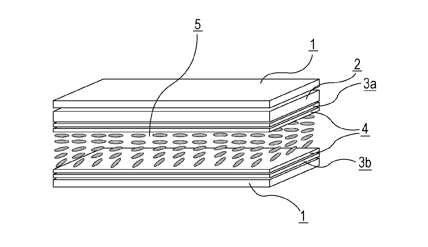
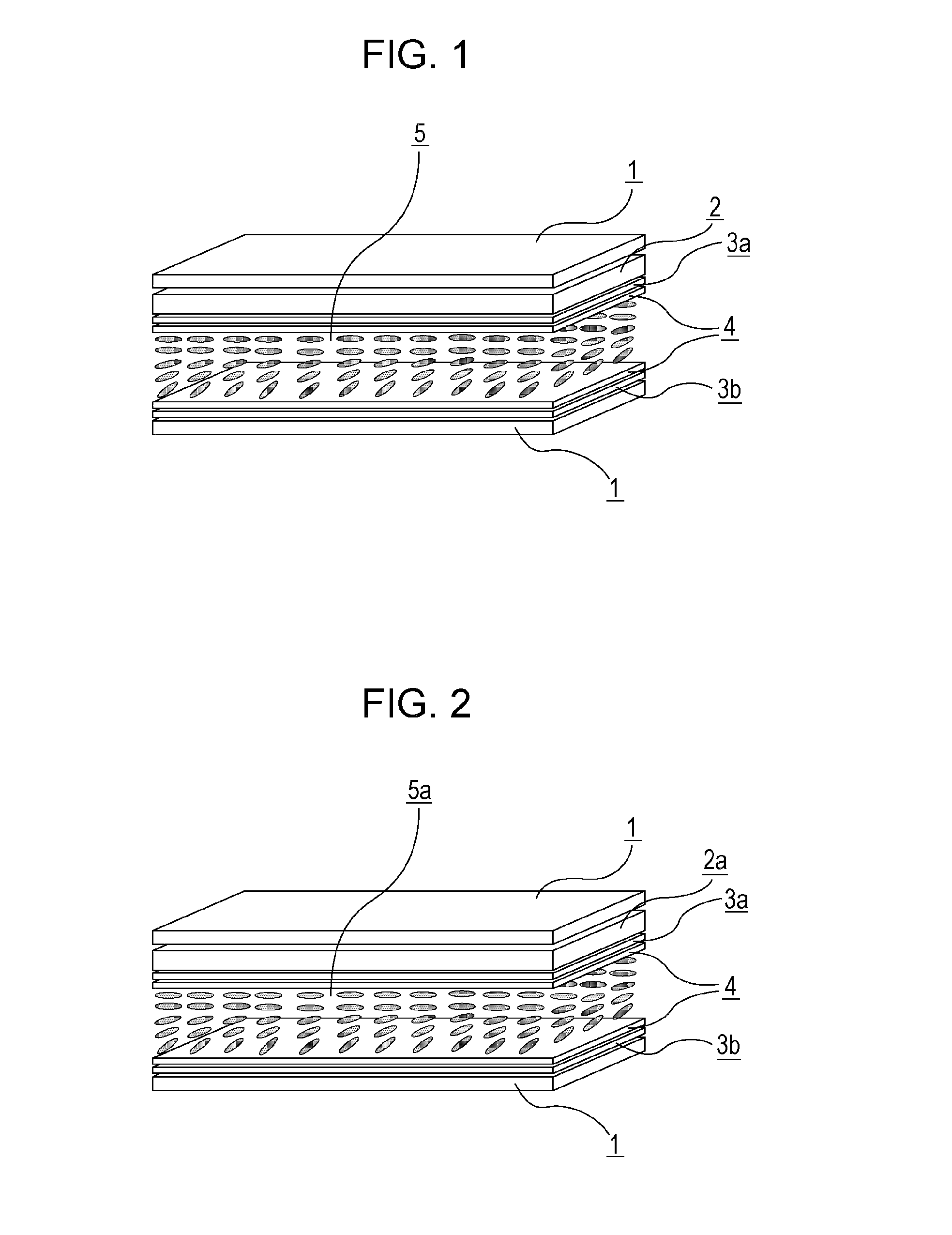
[0252]An electrode structure was formed on the first and second substrates, and an alignment film having a vertical alignment was formed on surfaces of the first and second substrates which faced each other. Subsequently, a rubbing treatment was performed to form a TN cell. The liquid crystal composition 1 shown in Table 9, which had a positive dielectric anisotropy, was held between the first and second substrates. Then, liquid crystal display apparatuses of Example 1 (dgap=3.5 μm, alignment film: AL-1051) were each prepared using a specific one of the color filters 1 to 4 shown in Table 8. The VHR and ID of each liquid crystal display apparatus were measured. Each liquid crystal display apparatus was evaluated in terms of burn-in. Table 10 summarizes the results.

TABLE 9Liquid crystalcomposition 15-Cy-Ph—F57-Cy-Ph—F62-Cy-Cy-Ph—OCFFF113-Cy-Cy-Ph3—F123-Cy-Cy-Ph—OCFFF123-Cy-Ph—Ph1—OCFFF124-Cy-Cy-Ph—OCFFF105-Cy-Cy-Ph3—F95-Cy-Cy-Ph—OCFFF125-Cy-Ph—Ph3—F11Total composition100proportionTni...

examples 5 to 16

[0258]A specific one of the liquid crystals shown in Table 15, which had a positive dielectric anisotropy, was held between the first and second substrates as in Example 1. Then, liquid crystal display apparatuses of Examples 5 to 12 were each prepared using a specific one of the color filters shown in Table 8. The VHR and ID of each liquid crystal display apparatus were measured. Each liquid crystal display apparatus was evaluated in terms of burn-in. Tables 16 to 18 summarize the results.

TABLE 15LiquidLiquidLiquidcrystalcrystalcrystalcomposi-composi-composi-tion 2tion 3tion 45-Cy-Ph—F5567-Cy-Ph—F6662-Cy-Cy-Ph—OCFFF1111113-Cy-Cy-Ph1—F123-Cy-Cy-Ph1—OCFFF93-Cy-Cy-Ph3—OCFFF123-Cy-Cy-Ph—OCFFF1212123-Cy-Ph—Ph1—F143-Cy-Ph—Ph1—OCFFF12124-Cy-Cy-Ph—OCFFF1010105-Cy-Cy-Ph1—F95-Cy-Cy-Ph1—OCFFF105-Cy-Cy-Ph3—OCFFF95-Cy-Cy-Ph—OCFFF1212105-Cy-Ph—Ph1—F125-Cy-Ph—Ph1—OCFFF1111Total composition100100100proportionTni / ° C.96.198.997.6Δn (20° C.)0.0910.0960.096Δε (20° C.)10.410.58.6

TABLE 16Example 5Examp...


PUM

PropertyMeasurementUnit
specific electrical conductivityaaaaaaaaaa

Abstract

There is provided a liquid crystal display apparatus that may limit a reduction in the voltage holding ratio (VHR) of a liquid crystal layer and limit an increase in the ion density (ID) in the liquid crystal layer and address issues of faulty display such as white missing pixels, alignment inconsistencies, and burn-in. Having a feature of limiting a reduction in the VHR of a liquid crystal layer and limiting an increase in an ion density (ID) in the liquid crystal layer and thereby reducing occurrence of faulty display such as burn-in, the liquid crystal display apparatus according to the present invention may be particularly suitably used as a VA-mode or PSVA-mode liquid crystal display apparatus for active-matrix driving and may be used as a liquid crystal display apparatus included in a liquid crystal TV, a monitor, a mobile phone, a smart phone, or the like.

Description

TECHNICAL FIELD[0001]The present invention relates to a liquid crystal display apparatus.BACKGROUND ART[0002]Liquid crystal display apparatuses have been widely used in clocks, electronic calculators, various home appliances, measuring equipment, panels for automobiles, word processors, electronic personal organizers, printers, computers, TVs, and the like. Common examples of liquid crystal display methods include a TN (twisted nematic) type, a STN (super-twisted nematic) type, a DS (dynamic light scattering) type, a GH (guest-host) type, an IPS (in-plane switching) type, an OCB (optically compensated birefringence) type, an ECB (electrically controlled birefringence) type, a VA (vertical alignment) type, a CSH (color super-homeotropic) type, and a FLC (ferroelectric liquid crystal). There has been a shift in the driving method used from a conventional static driving to a multiplex driving, which has been commonly employed. Simple-matrix liquid crystal displays and, recently, active...

Claims


Application Information

Patent Timeline
Patent Type & Authority Applications(United States)
IPC IPC(8): G02F1/1335C09K19/54C09K19/30
CPCG02F1/133514C09K19/3001G02F1/133512C09K19/542C09K19/3066C09K19/2014C09K19/322C09K19/60G02B5/20G02F1/1335C09K2019/0466C09K2019/0448C09K2019/523C09K2019/122C09K2019/123C09K2019/3021C09K2019/3016C09K2019/301C09K2019/3004C09K2019/304C09K2019/3037C09K2019/3036G02F1/13
Inventor KANEOYA, MASAKAZUTAKEUCHI, KIYOFUMIFUNAKURA, SEIJIOSHIUMI, ISAOSHIMADA, KATSUNORI
Owner DAINIPPON INK & CHEM INC
Why Eureka
Try Eureka