

Method and equipment for quantum vacuum energy extraction
- Summary
- Abstract
- Description
- Claims
- Application Information
AI Technical Summary
Benefits of technology
Problems solved by technology
Method used
Image

Examples
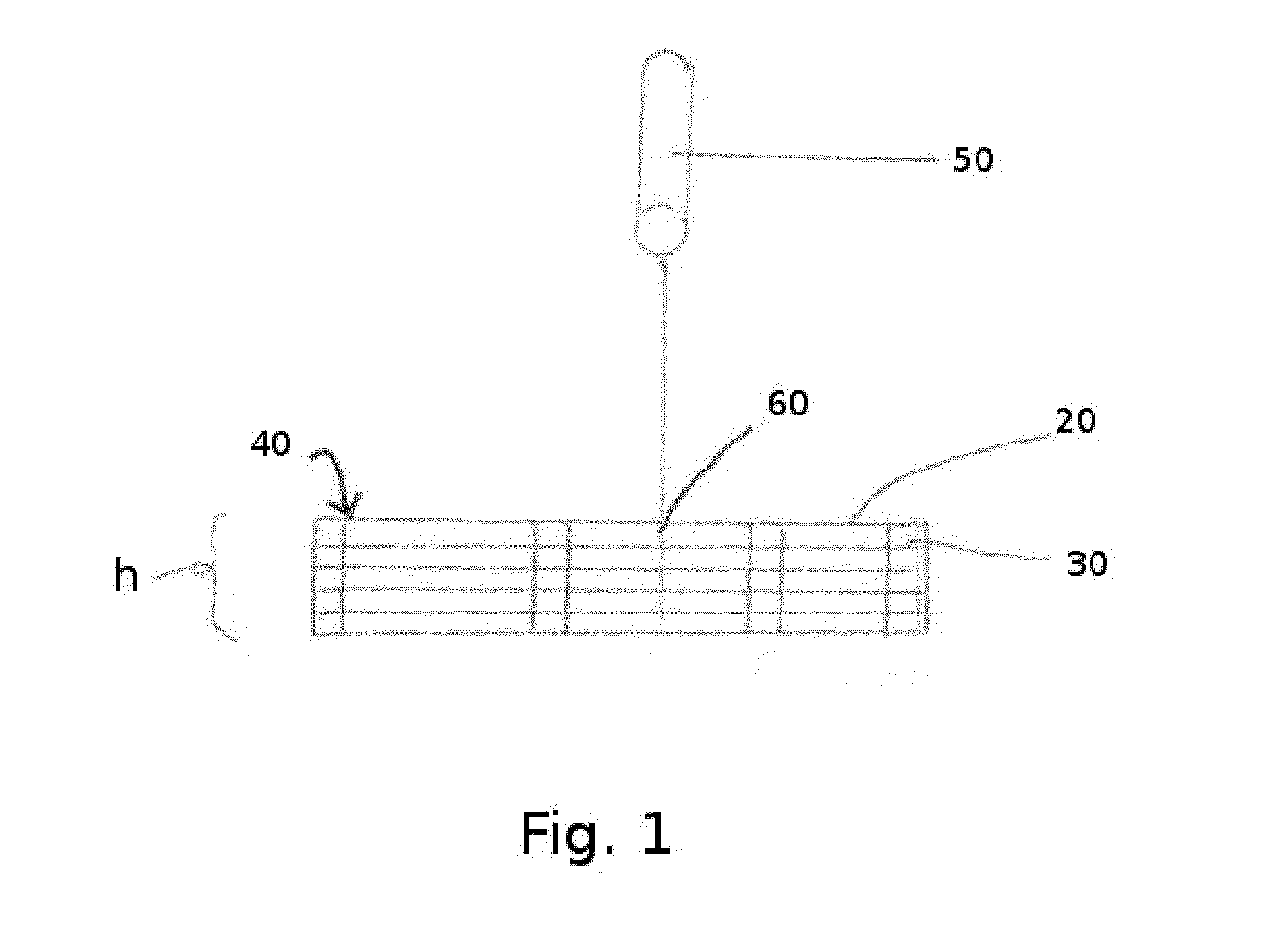
embodiment 100
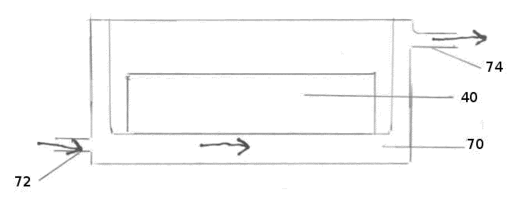
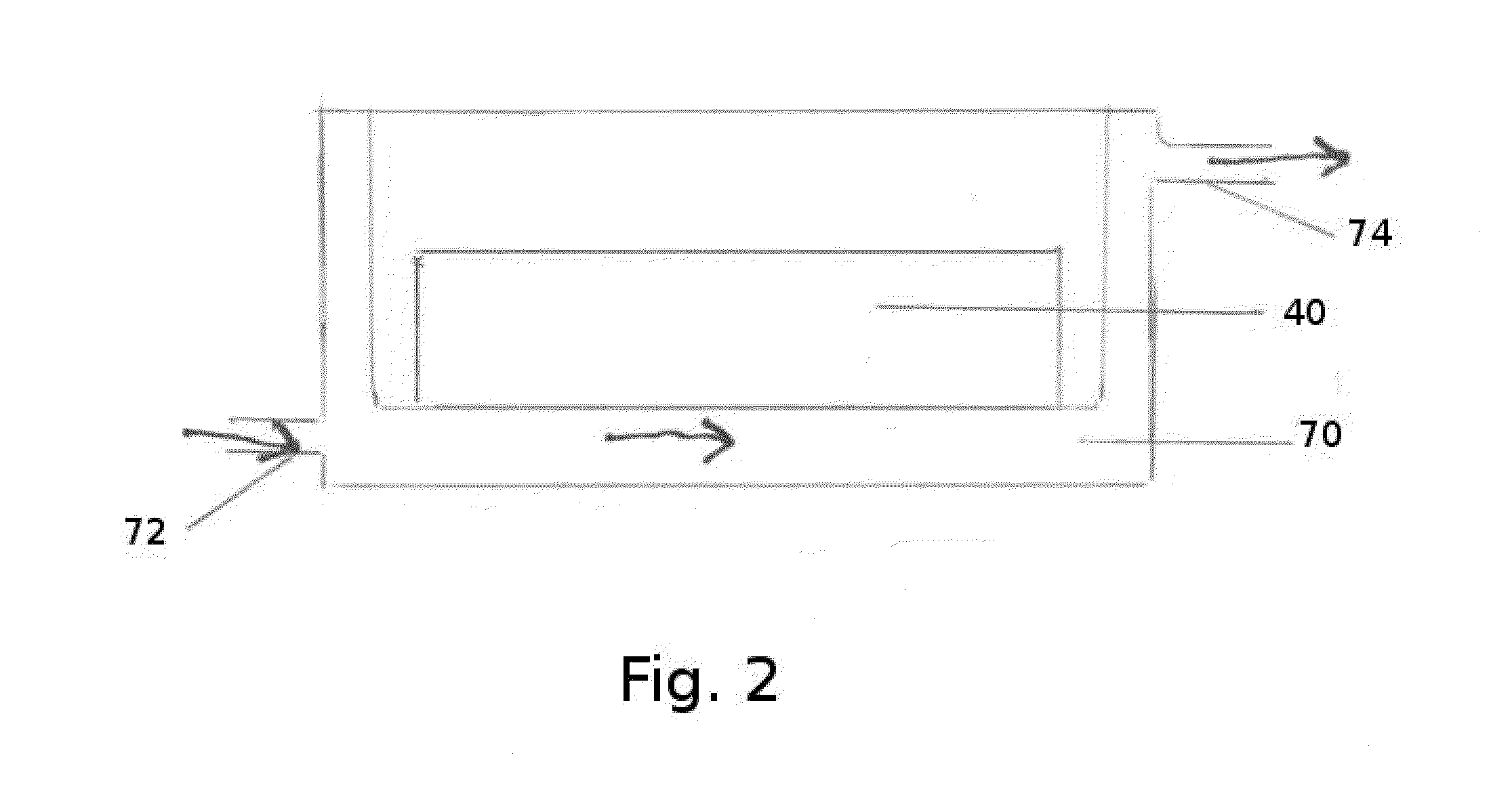
[0125]In this embodiment 100, a plurality of wires 110 may be bundled together and held together by a form fitting filter shell of conducting material 120 such that the fluid is forced through the conducting and non-conducting component.
[0126]The wires 110 may a have cross-section that is circular (round) or otherwise shaped as desired.
[0127]Because gaps will exist between the wires 110, even when packed together, the gaps 130 provide a channel through which gas can flow, and thereby effect a Casimir device (FIG. 3). The wires utilized may be commercially available wires having a narrow diameter, or wires extruded, drawn, rolled, spun, molded, or stamped to have thicknesses / diameters at either the sub-micron, micron, or millimeter size. The wires may be manufactured from any conducting material, such as, but not limited to aluminum, copper, silver, metallically doped or metallically coated non-conducting wire material. Non-conducting wires can be similarly prepared from a variety of...
embodiment 200
[0130]In this embodiment 200, a plurality of hollow tubes 210 may be bundled together and held together by a form fitting filter shell 220 of conducting material such that the fluid is forced through the conducting and non-conducting component.
[0131]Because gaps 230 will exist between the tubes, even when packed together, the gaps 230 provide a channel through which gas can flow, and thereby effect a Casimir device (see FIG. 6). The tubes 210 utilized may be commercially available tubes having a narrow diameter, or tubes produced by one or more prior-art processes similar to those described above for wires, as appropriate. The tubes 210 may have outer diameters at either the sub-micron, micron, or millimeter size. The tubes 210 may be manufactured from any conducting material, such as, but not limited to aluminum, copper, silver, metallically doped or metallically coated non-conducting material. Non-conducting tubes can be similarly prepared from a variety of non-conducting material...
PUM
| Property | Measurement | Unit |
|---|---|---|
| Size | aaaaa | aaaaa |
| Size | aaaaa | aaaaa |
| Size | aaaaa | aaaaa |
Abstract
Description
Claims
Application Information