
Reinforcement cord for reinforcing rubber product, and rubber product using same

a technology of reinforcing cords and rubber products, which is applied in the direction of ropes, cables, transportation and packaging of vehicles/pulleys, etc., can solve the problems of deterioration of the coating layer the tensile strength of the reinforcing cord decreases as the belt moves, and the reinforcing cord strength decreases. , to achieve the effect of good bending fatigue, good adhesion to the matrix rubber, and good

Active Publication Date: 2014-04-03
NIPPON SHEET GLASS CO LTD
View PDF4 Cites 12 Cited by
  • Summary
  • Abstract
  • Description
  • Claims
  • Application Information

AI Technical Summary

Benefits of technology

The present invention provides a reinforcing cord with good bending fatigue and adhesion to a matrix rubber using carbon fibers. This is achieved by limiting the total amount of crosslinking agent and filler in the treatment agent for forming the coating layer, which results in a flexible coating layer that allows for improved performance.

Problems solved by technology

A reinforcing cord using carbon fibers has a drawback that the tensile strength of the cord decreases as the belt moves.
One of the causes may be that the fibers in the reinforcing cord are locally broken due to local high stress concentration thereon during use, and thus the strength of the reinforcing cord decreases.
Another cause may be the deterioration of the coating layer of the reinforcing cord.
If the coating layer formed on the reinforcing fibers is hard, the load on the reinforcing fibers may increase when the reinforcing cord is subjected to bending deformation.
However, since the elastic modulus of the cord decreases if the number of twists is increased, such a cord cannot be used for applications that require high-modulus belts.

Method used

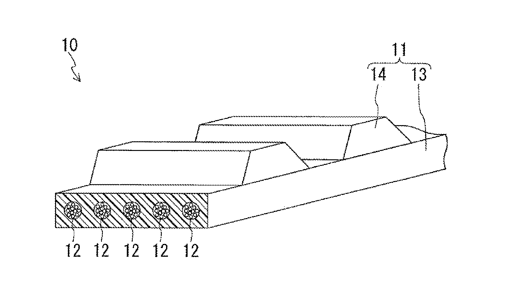
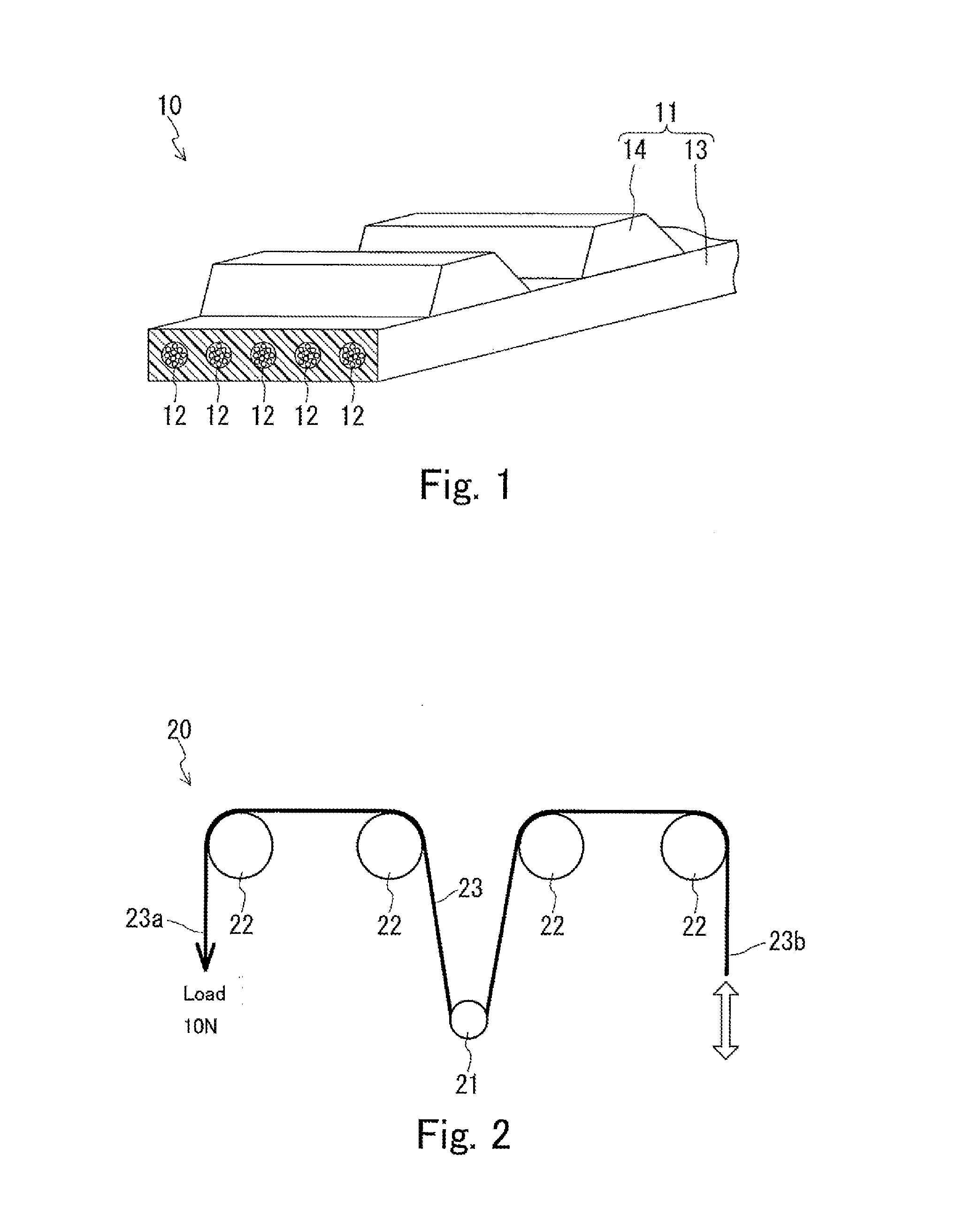

Image

  • Reinforcement cord for reinforcing rubber product, and rubber product using same
  • Reinforcement cord for reinforcing rubber product, and rubber product using same

Examples


examples

[0058]Hereinafter, the present invention is described in more detail by way of examples.

examples 1 to 11

[0059]First, 12000 carbon fiber filaments were bundled together to obtain a bundle of filaments. The carbon fiber filaments having an average diameter of 7 μm were used.

[0060]The resulting bundle was immersed in an aqueous treatment agent (A) having a composition shown in Table 1 below, and then dried at 200° C. for 2 minutes. Thus, one carbon fiber cord having the first coating layer was obtained. This carbon fiber cord was twisted at a rate of 60 times per meter in one direction. The composition ratio of each component shown in Table 1 is the composition ratio of the solid content of the component.

TABLE 1Examples1234567891011AqueousComposition ratioCarboxyl-modified hydrogenated10010010010010010050100100treatment(parts by mass)nitrile rubber latex (*1)agentCarboxyl-modified nitrile rubber latex10010050(*2)4,4′-bismaleimide diphenylmethane1051010110201010200Polyisocyanate1051010110201010020Silica51555Carbon black5Total of crosslinking agents (parts by mass)201020202204020202020Tota...


PUM

PropertyMeasurementUnit
Fractionaaaaaaaaaa
Fractionaaaaaaaaaa
Fractionaaaaaaaaaa

Abstract

The reinforcing cord of the present invention includes at least one strand. The strand includes a bundle of filaments that are bundled and twisted together in one direction, and a coating layer that is formed on at least the surface of the bundle. The bundle consists essentially of carbon fiber filaments. The coating layer is a coating layer that is formed from an aqueous treatment agent containing a rubber latex and a crosslinking agent as essential components and a filler as an optional component. In the aqueous treatment agent, the total of the mass of the crosslinking agent and the mass of the filler is in a range of 1 to 50% of the mass of rubber in the rubber latex.

Description

TECHNICAL FIELD[0001]The present invention relates to a reinforcing cord for reinforcing a rubber product and to a rubber product including the reinforcing cord.BACKGROUND ART[0002]A rubber belt or a chain is used for driving a camshaft of an internal combustion engine of an automobile, driving an auxiliary unit such as an injection pump, or power transmission in an industrial machine. Generally, a rubber belt includes a rubber portion and a reinforcing cord embedded in the rubber portion. Since the strength of the rubber belt depends on the strength of the reinforcing cord, the reinforcing cord is an important component that determines the life of the rubber belt. Typically, the reinforcing cord includes reinforcing fibers and a coating layer formed on the surface of the fibers. As examples of such a reinforcing cord, rubber belts in which carbon fibers are used as reinforcing fibers have been proposed (for example, JP 2004-225178 A and JP 2010-024564 A).[0003]A reinforcing cord us...

Claims


Application Information

Patent Timeline
IPC IPC(8): D02G3/36D02G3/02F16G1/08C08J5/06
CPCD02G3/36F16G1/08D02G3/02C08J5/06C08K3/04C08K3/36C08K7/02F16G1/28F16G5/06D06M15/693D06M2101/40F16G5/20D02G3/447D10B2101/12Y10T428/2918C08L21/02
Inventor FURUSAWA, MASAMORI
Owner NIPPON SHEET GLASS CO LTD
Learn More