Orthopaedic implants

a technology of orthopaedic implants and implants, applied in the field of orthopaedic implants, can solve the problems of limited success in wrist replacement of bones and joints, decreased joint mobility, damaged or diseased bones and joints, etc., and achieve the effect of reducing difficulties and disadvantages

Inactive Publication Date: 2014-04-03
MCGILL UNIV
View PDF6 Cites 58 Cited by
  • Summary
  • Abstract
  • Description
  • Claims
  • Application Information

AI Technical Summary

Benefits of technology

[0011]The present invention reduces the difficulties and disadvantages of the aforesaid designs and treatments.

Problems solved by technology

Damaged or diseased bones and joints in human and animal patients give rise to pain and decreased joint mobility.
The replacement of bones in the wrist has had limited success because of the complexity and multitude of bones, tendons and ligaments in the wrist.
Arthritis more commonly affects elderly patients and results in painful joints, and may be so severe that the pain cannot be managed with pain medication and the arthritic hand cannot be used to lift weight.
Damage or degeneration to the scaphoid bone can also occur through conditions other than fracture.
The scaphoid bone is particularly difficult to heal since blood supply to the scaphoid bone is provided only by vessels on the distal side.
If not treated properly or detected early, a scaphoid bone fracture can lead to bone necrosis.
These types of replacements can also loosen through trauma or injury sustained through a fall, for example, or through wear, and therefore require replacement.
Clearly, this can restrict the range of movement of the patient's wrist and is not ideal.
The bones of the human or animal foot can suffer from similar damage or diseases as the wrist.
As for the wrist, there is a lack of effective treatment for damaged or diseased foot bones and ligaments.

Method used


Image

  • Orthopaedic implants
  • Orthopaedic implants
  • Orthopaedic implants

Examples


example 1

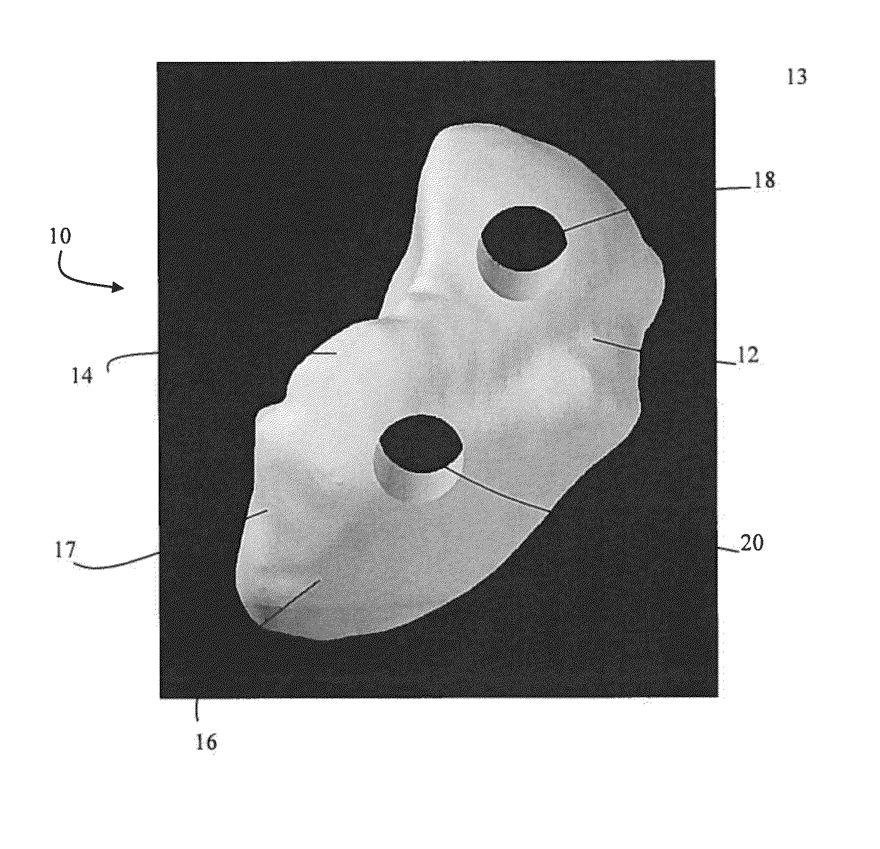
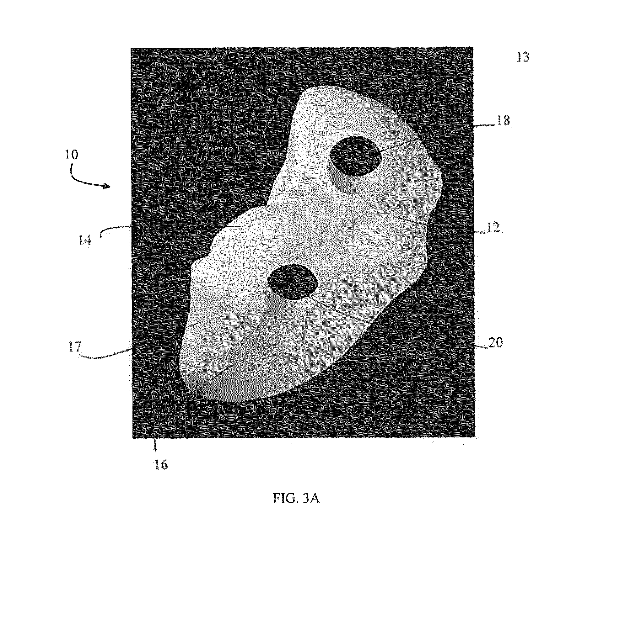
[0111]The scaphoid implant 10 of the present invention was made and implanted in the manner as described above into the wrist of a cadaver, including use of the cutting guide jigs.

[0112]FIGS. 26A and 26B, 27A and 27B, and 28A and 28B show x-rays taken of the cadaver's wrist after implantation and during maximum flexion and extension.

example 2

[0113]The inventors performed a cadaveric study using MRI and CT on the symmetry of contralateral scaphoid bones. Surprisingly, they found that the contralateral scaphoid bones are mirror images of one another, as determined by four geometrical features: 1) long axis, 2) waist length, 3) distal pole and 4) proximal pole (FIG. 29A).

[0114]A CT and MR investigation of 12 pairs of cadaveric wrists was made in neutral position. After imaging, each wrist was dissected and the bones were cleaned of any connective tissue. The bones were measured along their longest axis and the volume of each bone was determined by water displacement measurements.

[0115]Lunate Measurements[0116]Antero-dorsal diameter (16.96 mm±1.6)[0117]Medio-lateral diameter (12.8 mm±1.37)[0118]Height / max length[0119]Volume[0120]Surface Area.

[0121]Scaphoid Measurements[0122]Height / Max length[0123]Volume[0124]Surface Area.

[0125]A statistical analysis was carried using the Pearson correlation coefficient comparing CT / MRI and ...


PUM

PropertyMeasurementUnit
diameteraaaaaaaaaa
diameteraaaaaaaaaa
Magnetic Resonance Imagingaaaaaaaaaa

Abstract

A method for making an orthopaedic implant, the method comprising: characterizing at least a portion of a bone corresponding to the bone to be replaced, said corresponding bone being on the contralateral side of the patient; providing a model of the orthopaedic implant based on a mirror image of the contralateral bone; and forming the orthopaedic implant based on the model.

Description

CROSS REFERENCE TO RELATED APPLICATIONS[0001]This is a divisional of U.S. patent application Ser. No. 12 / 809,030 filed Sep. 3, 2010, which is a U.S. National Phase entry of International Patent Application No. PCT / CA2008 / 002179 filed Dec. 17, 2008, which claims the benefit of U.S. Provisional Patent Application No. 61 / 008,173 filed Dec. 18, 2007. Each of these applications are incorporated herein in their entirety.FIELD OF THE INVENTION[0002]The invention relates generally to orthopaedic implants, methods of making the orthopaedic implants, methods of implanting the orthopaedic implants, devices for implanting the orthopaedic implants and devices for assisting cutting bone.BACKGROUND OF THE INVENTION[0003]Damaged or diseased bones and joints in human and animal patients give rise to pain and decreased joint mobility. It is known to totally or partially replace these bones and joints with artificial implants to alleviate the painful symptoms and restore some degree of mobility.[0004]...

Claims


Application Information

Patent Timeline
Patent Type & Authority Applications(United States)
IPC IPC(8): A61F2/30A61F2/42
CPCA61F2/4261A61F2/30942A61B6/505A61B17/15A61B2034/102A61F2/28A61F2002/2871A61F2002/30069A61F2002/30943A61F2002/30948A61F2002/30957A61F2002/4289A61F2240/004A61F2310/00011A61F2310/00179B33Y50/00B33Y80/00Y10T29/49
Inventor HACKING, ADAM S.HARVEY, EDWARD J.RICHARDS, COREY
Owner MCGILL UNIV
Why Eureka
Try Eureka