Debris filter with splitter box

a technology of filter box and filter shell, which is applied in the direction of gravity filter, loose filtering material filter, stationary filter element filter, etc., can solve the problems of reducing heat transfer, affecting power generation, and large water quantity, and achieves simplified shell construction, enhanced rigidity, and simplified mounting system for filter screen.

Active Publication Date: 2014-04-10
OVIVO INC
View PDF132 Cites 23 Cited by
  • Summary
  • Abstract
  • Description
  • Claims
  • Application Information

AI Technical Summary

Benefits of technology

[0023]Another advantage of the present invention is a simplified shell construction owing to a simplified mounting system for the filter screen. The use of a mounting ring reinforces the filter shell, housing or casing, enhancing shell rigidity, while providing a simplified attachment of the filter screen to the shell.
[0024]The screen ribs in a debris filter in accordance with the present invention act as flow straighteners that assist in transporting less turbulent flow thro

Problems solved by technology

The quantity of water required is quite large and it contains debris like grass, shells, fish, cloth and plastic sheet material.
Such debris tends to clog the tubes of the steam condensers, causing reduction in heat transfer, which in turn may affect power generation.
The problem of accumulation of debris and the need for p

Method used


Image

  • Debris filter with splitter box
  • Debris filter with splitter box
  • Debris filter with splitter box

Examples


Embodiment Construction

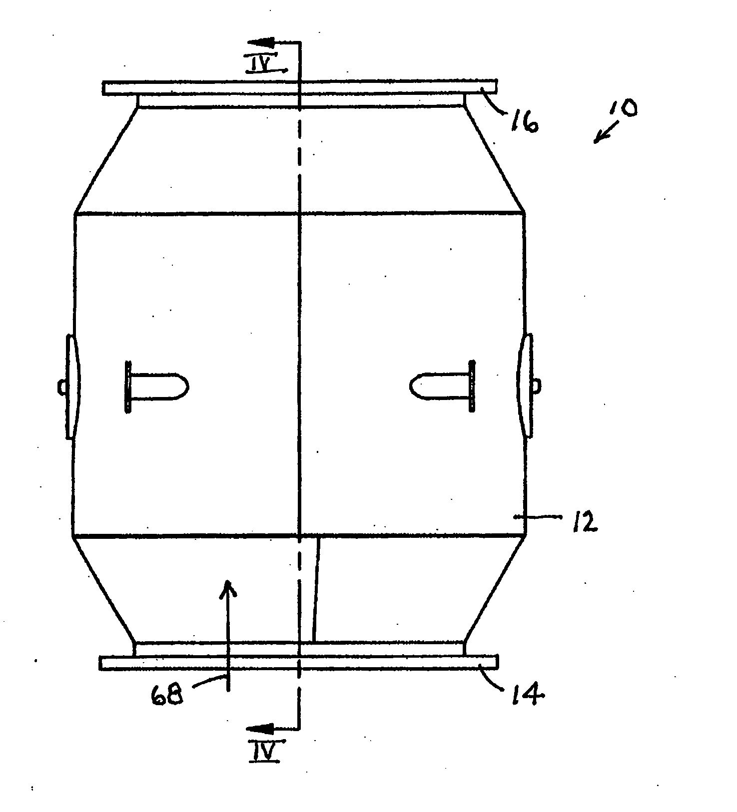
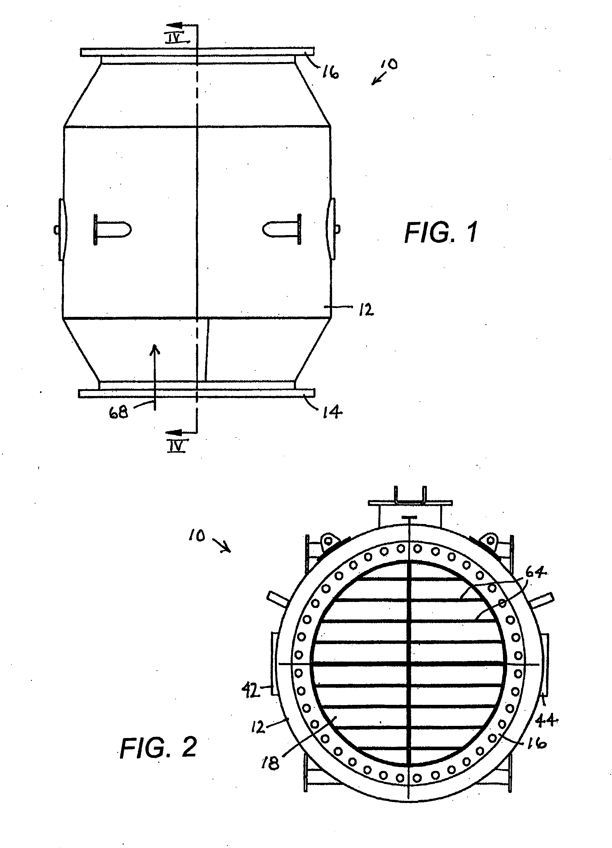
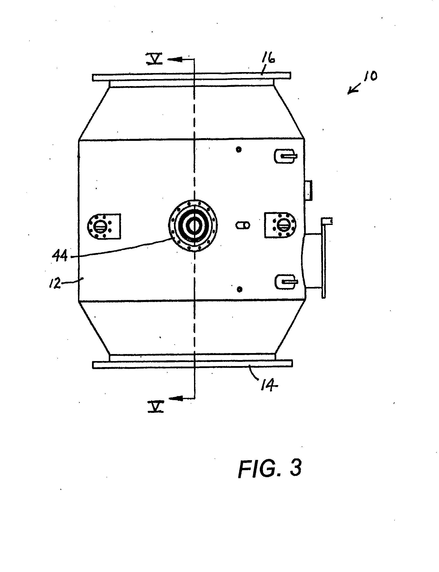
[0035]A debris filter 10 comprises a substantially cylindrical housing, shell or casing 12 provided at opposite, conically tapered, ends with an annular inlet flange 14 and an annular outlet flange 16 for coupling the shell or housing to an upstream pipe section (not shown) and a downstream pipe section (not shown), respectively. A spherical filter screen 18, typically made of stainless steel mesh on a stainless steel frame, is mounted to an inner surface 20 of shell or housing 12 via a connector ring 22 (FIGS. 4, 6, 7) welded thereto and extends across a path 68 (FIGS. 1, 4) of fluid flow through the debris filter. Filter screen 18 is concave on an upstream side and defines a filter zone 24 (FIG. 4). Filter zone 24 is at least substantially hemi-spherical and is defined or bounded on an upstream side by a plane 26 defined by a leading circular edge 28 of filter screen 18 or, concomitantly, connector ring 22.

[0036]Debris filter 10 further comprises a rotatable debris extractor or sc...


PUM

PropertyMeasurementUnit
Flow rateaaaaaaaaaa

Abstract

A debris filter has a housing, a filter screen mounted to the housing and disposed so as to extend across a flow path through the housing, a debris extractor mounted to the housing, and a splitter bar also mounted to the housing. The debris extractor and the filter screen are so mounted to the housing as to enable rotation of the filter screen and the debris extractor relative to one another. The debris extractor has a debris intake opening and the debris extractor and the splitter bar are so mounted to the housing that the intake opening is positionable adjacent to or in juxtaposition with the splitter bar with the splitter bar overlapping and shielding the intake opening.

Description

FIELD OF INVENTION[0001]This invention relates to a debris filter with rotatable debris extractor. In addition, this invention provides a system and a method of operating a debris filter.BACKGROUND OF THE INVENTION[0002]Thermal and nuclear power plants use steam condensers for condensation of steam after the energy has been utilized to drive the turbine(s). The steam condensers may be water-cooled or air-cooled. In water-cooled process, water is typically obtained from sources like sea, rivers and lakes. The quantity of water required is quite large and it contains debris like grass, shells, fish, cloth and plastic sheet material. Such debris tends to clog the tubes of the steam condensers, causing reduction in heat transfer, which in turn may affect power generation. The problem of accumulation of debris and the need for periodic removal of debris poses a serious challenge to the power generating plants. To overcome this problem, an automatic debris filter is installed at the inlet...

Claims


Application Information

Patent Timeline
IPC IPC(8): B01D33/00
CPCB01D29/035B01D29/682B01D29/688B01D2201/082
Inventor BROWNING, ANDREW L.
Owner OVIVO INC
Why Eureka
Try Eureka