Seal-bearing assembly

a technology of sealing and bearings, applied in the direction of machines/engines, liquid fuel engines, light and heating apparatus, etc., can solve the problems of high radial load on the sealing materials within the stuffing box, pressure affecting the adjacent textile ring,

Active Publication Date: 2014-04-17
SEAL RYT CORP
View PDF25 Cites 6 Cited by
  • Summary
  • Abstract
  • Description
  • Claims
  • Application Information

AI Technical Summary

Benefits of technology

[0008]Generally speaking, in accordance with the invention, a shaft seal-bearing assembly for use in the stuffing box of a mechanical device having a cylindrical member driven by a motor is provided. The assembly includes a pair of outer substantially rigid cylindrical bearings having an inner bore to be positioned over the cylindrical member and at least one complimentary flexible packing ring disposed between the two outer bearings. The inner bores of the bearings provide a bearing surfa

Problems solved by technology

However, due to the clearance some of the system pressure affects the adjacent textile

Method used


Image

  • Seal-bearing assembly
  • Seal-bearing assembly
  • Seal-bearing assembly

Examples


example 1

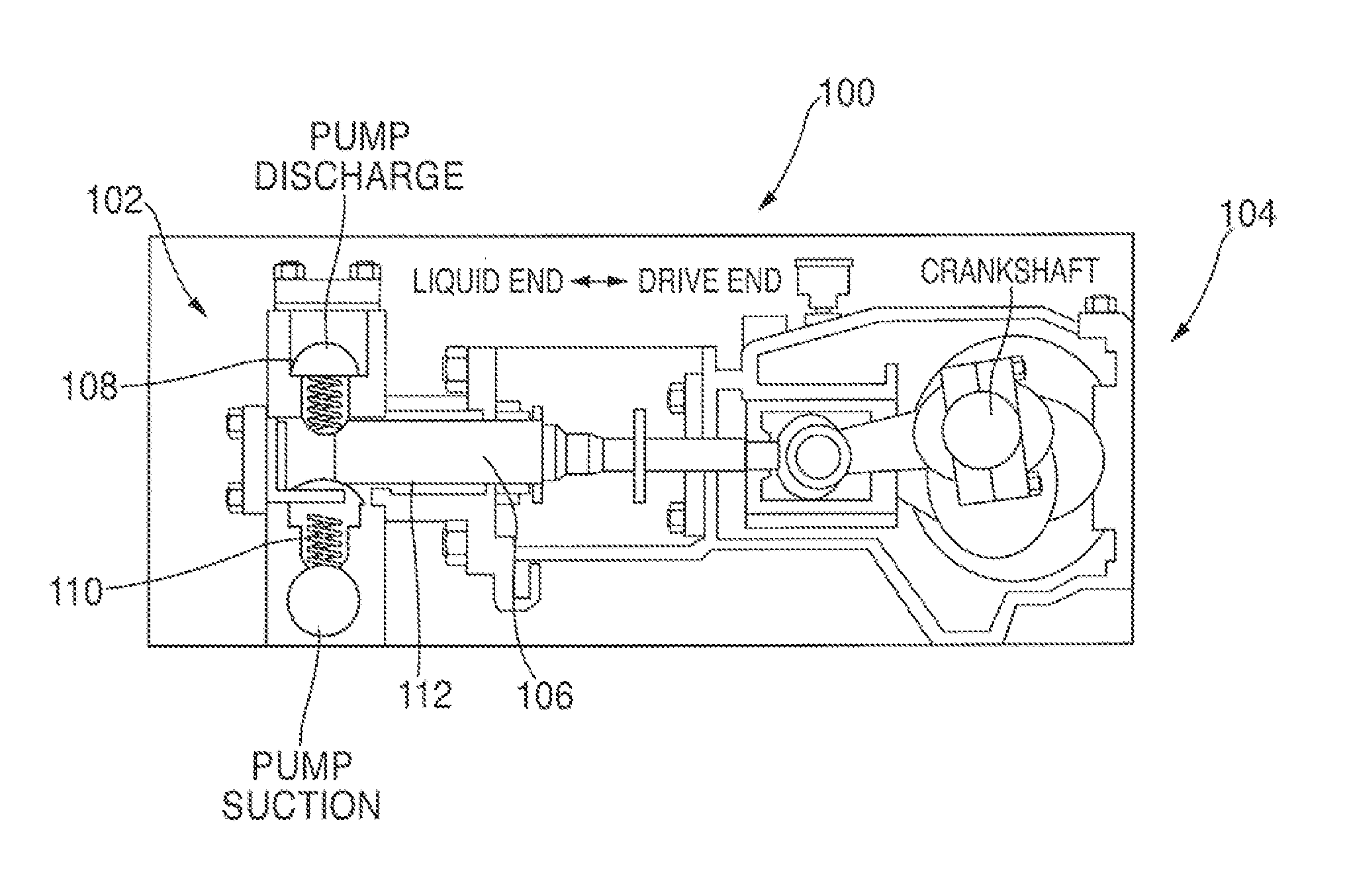
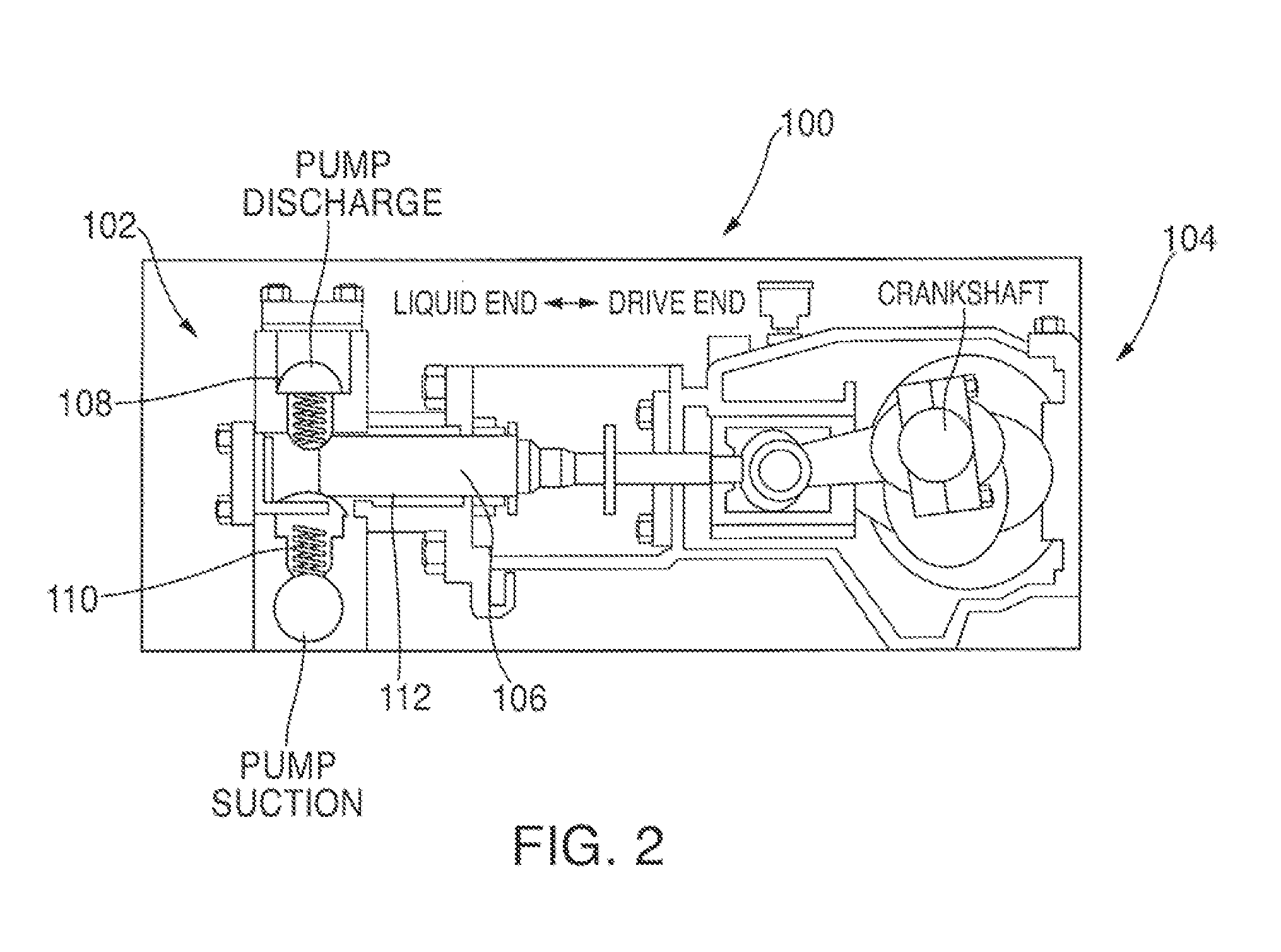
[0093]A bearing assembly in accordance with the invention suitable for use in a reciprocating device is prepared as follows. Such devices include a piston pump commonly used in the mining industry where slurries carrying abrasive rigid material are being transported. This abrasive material will dictate the type of bearing and packing used in the bearing assembly.

[0094]A typical stuffing box of a piston pump is 4.75 inches in depth with a casing having an inner bore of 3.25 inches and a piston shaft with a 2.50 inch diameter. Thus, the cross-section of the bearing assembly is 0.375 inch in length.

[0095]A 1.75 inch spring under tension is positioned at the upper end of the stuffing box. The assembly dimensions are 2.50″ (i.d.)×3.25″ (o.d.) / 0.375″ cross-section so that it fits into the annulus between the piston shaft and the inner bore of the stuffing box casing. The assembly includes a first bearing of an extended wear material, such as polyphenylene sulfide polymer compound 1.125 in...

example 2

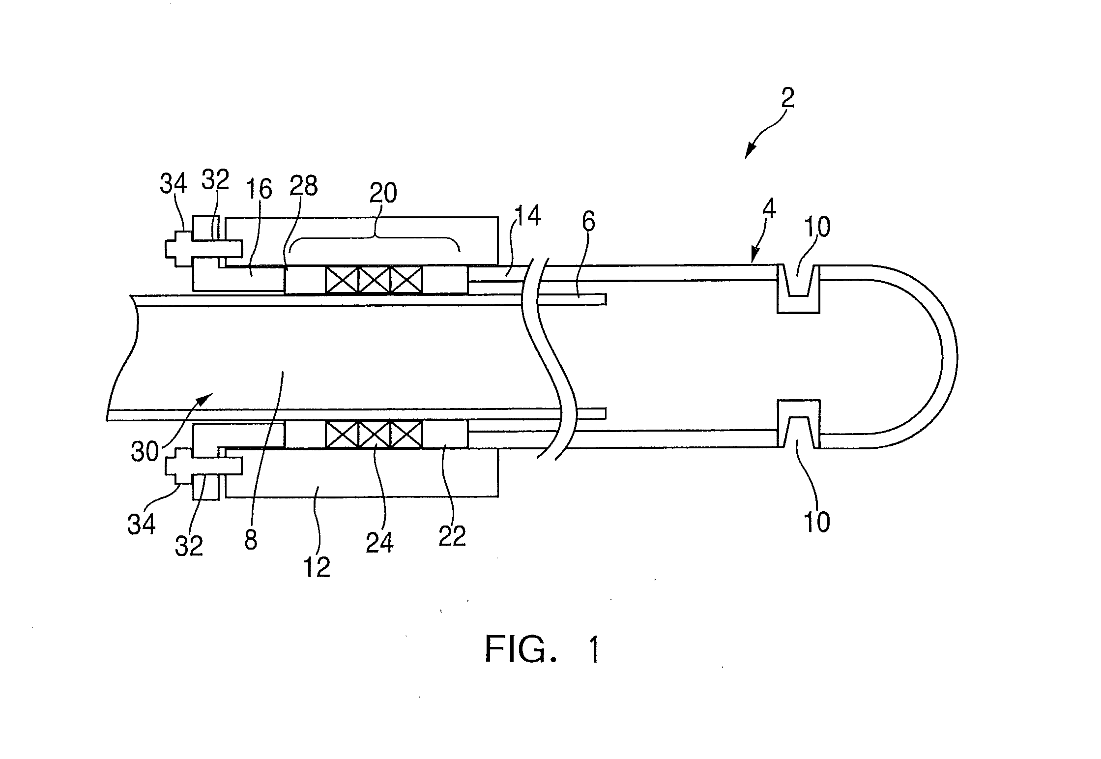
[0098]A bearing assembly in accordance with the invention suitable for use in the stuffing box of a rotary and reciprocal device such as a soot blower is prepared as follows. Such devices include a horizontally elongate steam supply tube and a horizontally elongate steam discharge lance telescoped axially over the supply tube. Such devices generally operate at temperatures over 600° F.

[0099]A typical stuffing box of a rotary soot blower is 3.375 inches in length with a casing having an inner bore of 3.125 inches and an inner supply tube having an outside diameter of 2.375 inches. Thus, the cross-section of the device is 0.375 inches. The bearing assembly includes two outer bearing rings formed of a high temperature polybenzimidazole material with textile packing elements between the bearings.

[0100]The assembly includes two outer bearings of a high temperature polybenzimidazole material, each 0.875 inches in length. Packing is placed between the two bearings. The packing includes a f...


PUM

PropertyMeasurementUnit
Timeaaaaaaaaaa
Lengthaaaaaaaaaa
Lengthaaaaaaaaaa

Abstract

A seal-bearing assembly to be inserted into the seal cavity of a mechanical device to provide a seal and a bearing surface to eliminate whip in a rotating and/or reciprocal cylindrical member. The seal-bearing assembly is particularly well suited for use in a reciprocal pump and between the steam lance and fixed steam tube in a sootblower. The assembly includes at least a pair of outer substantially rigid cylindrical bearings having an inner bore to be positioned over the cylindrical member and at least one complimentary flexible textile packing ring disposed between the two outer bearing members. In assemblies including an additional bearing, it is surrounded by at least one flexible packing on each side. The inner bore of the bearing members provide a bearing surface for eliminating whip of the moving elements in the device.

Description

CROSS-REFERENCE TO RELATED APPLICATION[0001]This application is based upon and claims the benefit of the filing date of co-pending, commonly owned U.S. Provisional Patent Application Ser. No. 61 / 614,914, filed Mar. 23, 2012, which is incorporated herein by reference in its entirety.FIELD OF THE INVENTION[0002]This invention relates to an improved sealing and bearing assembly for mechanical devices requiring a shaft seal and bearing support. More particularly, this invention relates to an improved seal-bearing assembly, which permits rotational and axial movement and is positioned in a seal cavity or stuffing box of a mechanical device such as a reciprocating pump or a sootblower.BACKGROUND OF THE INVENTION[0003]In mechanical devices, such as pumps driven by a shaft connected to a motor or other means to move fluids, the shaft passes through a seal cavity, or a “stuffing box,” defined by a cylindrical cavity in the device housing. The shaft is supported by bearings at the motor end. ...

Claims


Application Information

Patent Timeline
IPC IPC(8): F16C17/12
CPCF16C17/12F16C29/02F16C33/201F04B53/143F04B53/144F16J15/22F28G15/02F16C33/24F16C33/74F16C2208/20F16C2300/28F16J15/184F16J15/30F16J15/32
Inventor THOMA, LYNNE A.WILKINSON, MARK R.
Owner SEAL RYT CORP
Why Eureka
Try Eureka