Suture Passer and Subcortical Knot Placement

a subcortical knot and passer technology, applied in the field of suture passer and subcortical knot placement, can solve the problems of insufficient stiffness to push bone, marrow or other debris in a transosseous exchange, and the risk of migration of the suture anchor placed in the bone,

Inactive Publication Date: 2014-04-17
MICROAIRE SURGICAL INSTR
View PDF8 Cites 12 Cited by
  • Summary
  • Abstract
  • Description
  • Claims
  • Application Information

AI Technical Summary

Benefits of technology

This patent describes a new method for repairing tissue to bone using sutures. The invention provides a suture passer that is easy to use and can be preloaded with sutures. The method also includes using a bone tunnel to secure the tissue to the bone and minimize the likelihood of the sutures cutting through the bone. The invention also plays a role in achieving a high initial fixation strength and minimizing gap formation through subcortial transsoeous knots. Overall, the invention simplifies the surgical procedure and reduces the likelihood of complications.

Problems solved by technology

Suture anchors placed in the bone have the drawbacks including risks of migration, implant breakage and or adverse reactions to the anchor material.
In addition to the invasiveness of presently used surgical methods it is often difficult to pass the flexible sutures though the lumen of a drill guide.
Historically, suture used in rotator cuff repair is braided suture thus pushing it forward is as difficult as “pushing a rope.” Therefore, waxes and coatings have been used to facilitate this pushing by making suture more stiff.
Although these coatings stiffen suture, it is not always stiff enough to push bone, marrow or other debris in a transosseous exchange.
Once sutures are placed in bone, by any method, suturing soft tissue to the bone is sometimes a second problem.
Often, this is a mattress or other multi pass stitch that requires additional suturing devices and time.
These convenient locations do not addressed the issue of knot impingement on the undersurface of the acromion or diminish the concerns of critics.
Despite recent statements of equivalence comparing suture anchors and transosseous methods, a marketing based criticism of transosseous rotator cuff repair is “sutures may cut through bone.” Cutting though bone is a failure mode that is debatable and involves complicated biomechanical and outcome research.
Sutures can cut soft bone and suture anchors can fail in many ways.
The engineering challenge is minimization of these risks.
When a suture does cut through bone, it first needs a starting point and increasing the diameter of what must first pull through bone increases the force needed to initiate this potential problem.
Subcortcial knot placement greatly increases the diameter of the repair construct at this critical location thus the failure force required.

Method used


Image

  • Suture Passer and Subcortical Knot Placement
  • Suture Passer and Subcortical Knot Placement
  • Suture Passer and Subcortical Knot Placement

Examples


Embodiment Construction

[0048]The present invention now will be described more fully hereinafter with reference to the accompanying drawings, in which preferred embodiments of the invention are shown. This invention may, however, be embodied in many different forms and should not be construed as limited to the embodiments set forth herein; rather, these embodiments are provided so that this disclosure will be through and complete, and will fully convey the scope of the invention to those skilled in the art.

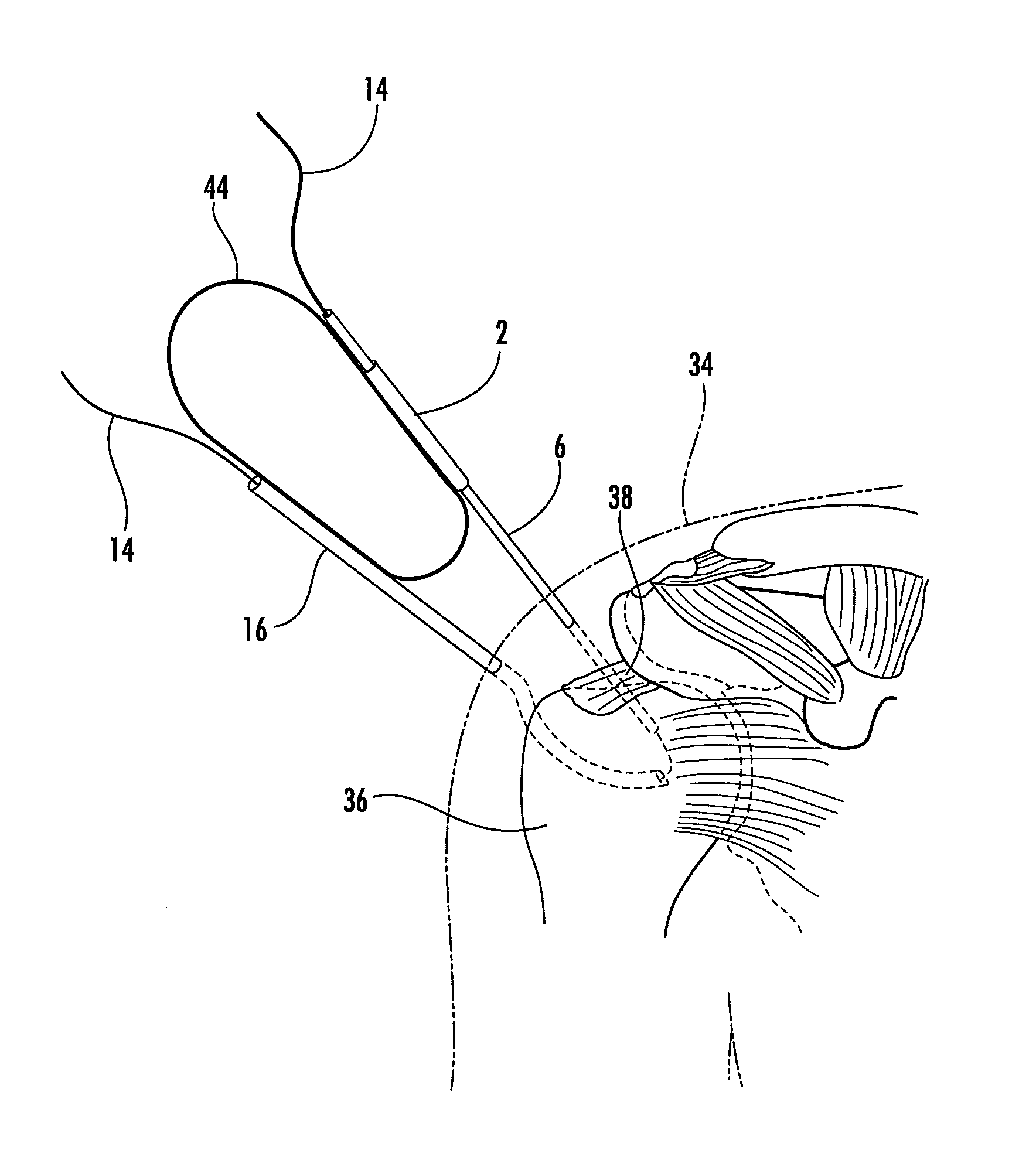
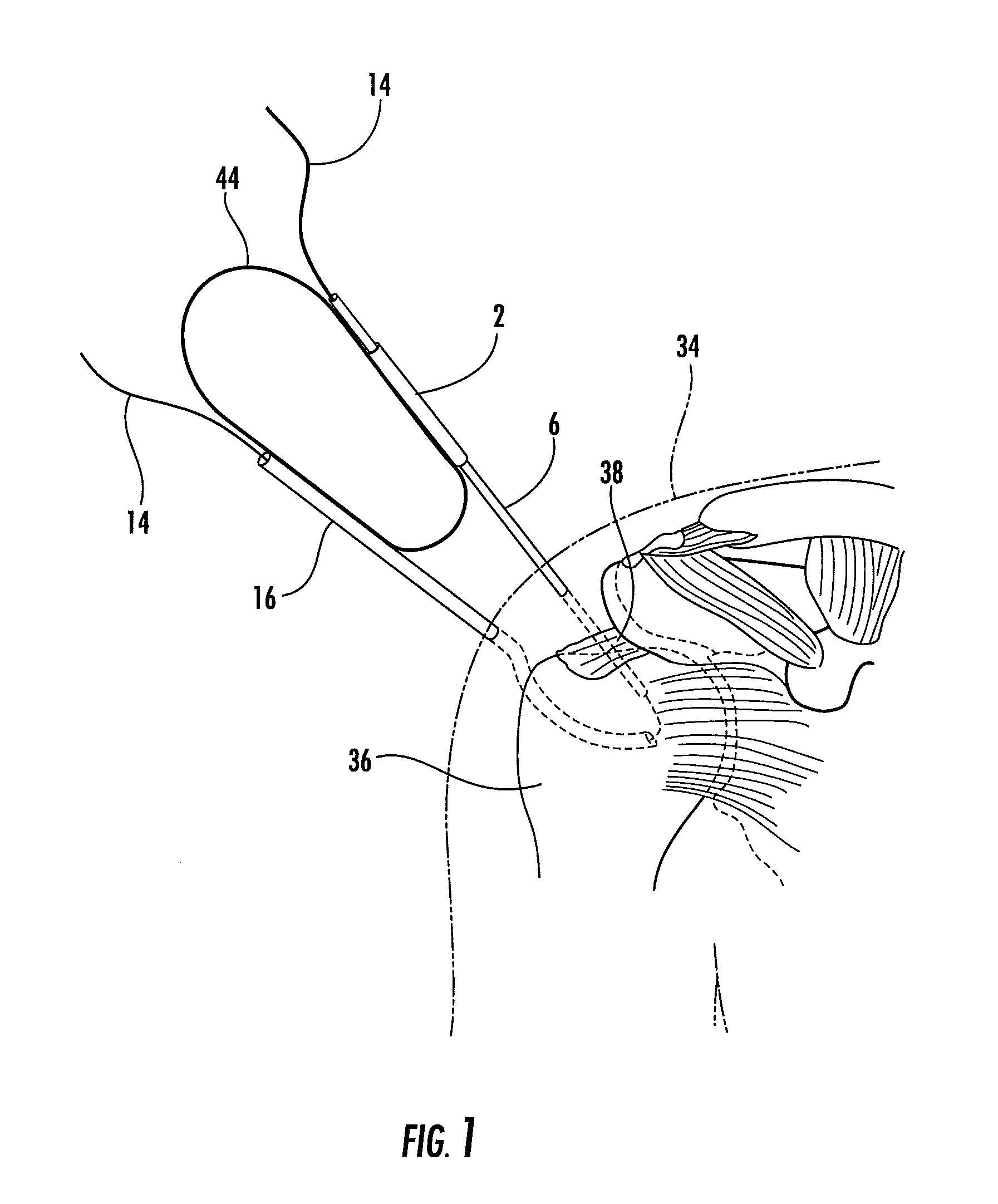
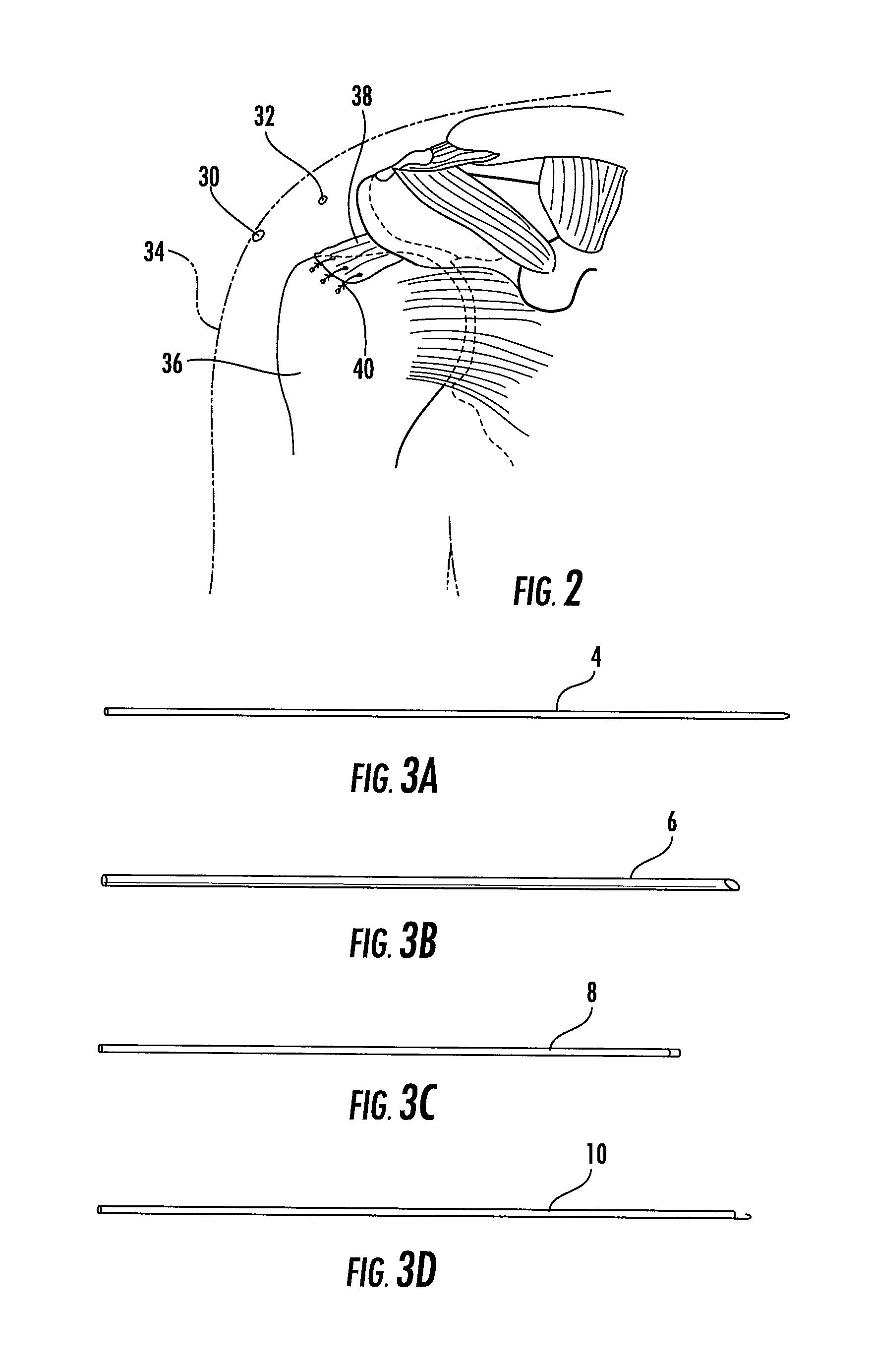
[0049]Referring now to the drawings there is shown in FIG. 1 a handle 44 that is used to maintain drill guides 2 and 16 at relative angles for the arthroscopic formation of tunnels. Two arthroscopic portals 30, 32 (shown in FIG. 2) are formed in the shoulder 34, such as by a scalpel. The humeral head 36 and rotator cuff tendons 38 are present. A stand of suture material 14 is shown passing through the drill guide, rotator cuff tissue, into and out of the humeral head, and exiting the central lumen of the...


PUM


Abstract

A suture passer (121) and method of using for the exchange of sutures between sections of a device used for attachment of tissue to bone or delivering suture to a separate device with the purpose of pushing then pulling suture through a plane of bone and / or tissue. In one embodiment a U-shaped or teardrop-shaped ridged material (18) (solid wire, braided wire, monofilament extruded polymer) stiffer than the intended suture material is used to pass the suture. Suture material or passing loops may be further contained in a preloaded tube or slotted tube that provides additional stiffening and the elimination of surgical steps. In another embodiment, a method of subcortical-transosseous knot placement is described which increases the load bearing and eliminates post surgical impingement with the acromion.

Description

CROSS-REFERENCE TO RELATED APPLICATION[0001]The contents of provisional Application U.S. Ser. No. 61 / 499,329 filed Jun. 21, 2011, on which the present application is based and benefit claimed under 35 U.S.C. §119(e), is herein incorporated by reference.BACKGROUND OF THE INVENTION[0002]1. Field of the Invention[0003]This invention relates generally to a timesaving suture passer and its use in arthroscopic transosseous rotator cuff repair to increase repair strength. More particularly, this invention relates to methods and devices for the exchange of suture(s) between sections of a device or delivering suture(s) to a separate device with the purpose of pulling suture(s) through a plane of bone and / or tissue and where benefits of a subcortical knot are realized if used with tunnels of sufficient diameter.[0004]2. Description of the Prior Art[0005]Invasive and open surgery methods of attachment of tissue to bone to repair tissue is well-known. Arthroscopy has become the preferred approa...

Claims


Application Information

Patent Timeline
IPC IPC(8): A61B17/04
CPCA61B17/0483A61B17/0482A61B17/0485A61B2017/00292A61B90/92
Inventor DROSS, BRIAN D.
Owner MICROAIRE SURGICAL INSTR
Why Eureka
Try Eureka