
Data storage architecture and system for high performance computing

a data storage and high-performance computing technology, applied in the data field, can solve problems such as system delays, system risk of corrupting files, zest and plfs have significant deficiencies,

Active Publication Date: 2014-04-17
DATADIRECT NETWORKS
View PDF3 Cites 33 Cited by
  • Summary
  • Abstract
  • Description
  • Claims
  • Application Information

AI Technical Summary

Benefits of technology

The patent text describes a data storage system for high-speed super computers that improves throughput and reduces latency. The system uses a parallel log-structured file system and a network RAID scheme to access data quickly. The system includes a data storage system coupled with a super computer, which stores data in a hierarchical manner to make it easily accessible. The system also includes a preliminary action flow chart to describe the steps taken to store or get data in the system. The technical effects of the patent text include improved data storage and retrieval speeds, reduced latency, and improved performance of super computers.

Problems solved by technology

In these file systems, clients acquire a lock before updating a file or portion thereof, otherwise, the system risks corrupting files when two or more clients attempt to update the same page simultaneously.
When large amounts of data are created quickly, Zest and PLFS have significant deficiencies when a data item must be accessed.
In Zest, the system incurs delays while waiting for data to be written to primary before being accessed.
In PLFS, data stored in buffer memory may be accessed, but it is indexed linearly such that significant time delays are incurred in identifying the location of data to be read from a buffer in PLFS systems.
This approach suffers from serialization in that only one client may modify a given region at any one time.
Further, this scheme is susceptible to a large degree of read-modify-writes which causes performance degradation.

Method used


Image

  • Data storage architecture and system for high performance computing
  • Data storage architecture and system for high performance computing
  • Data storage architecture and system for high performance computing

Examples


first embodiment

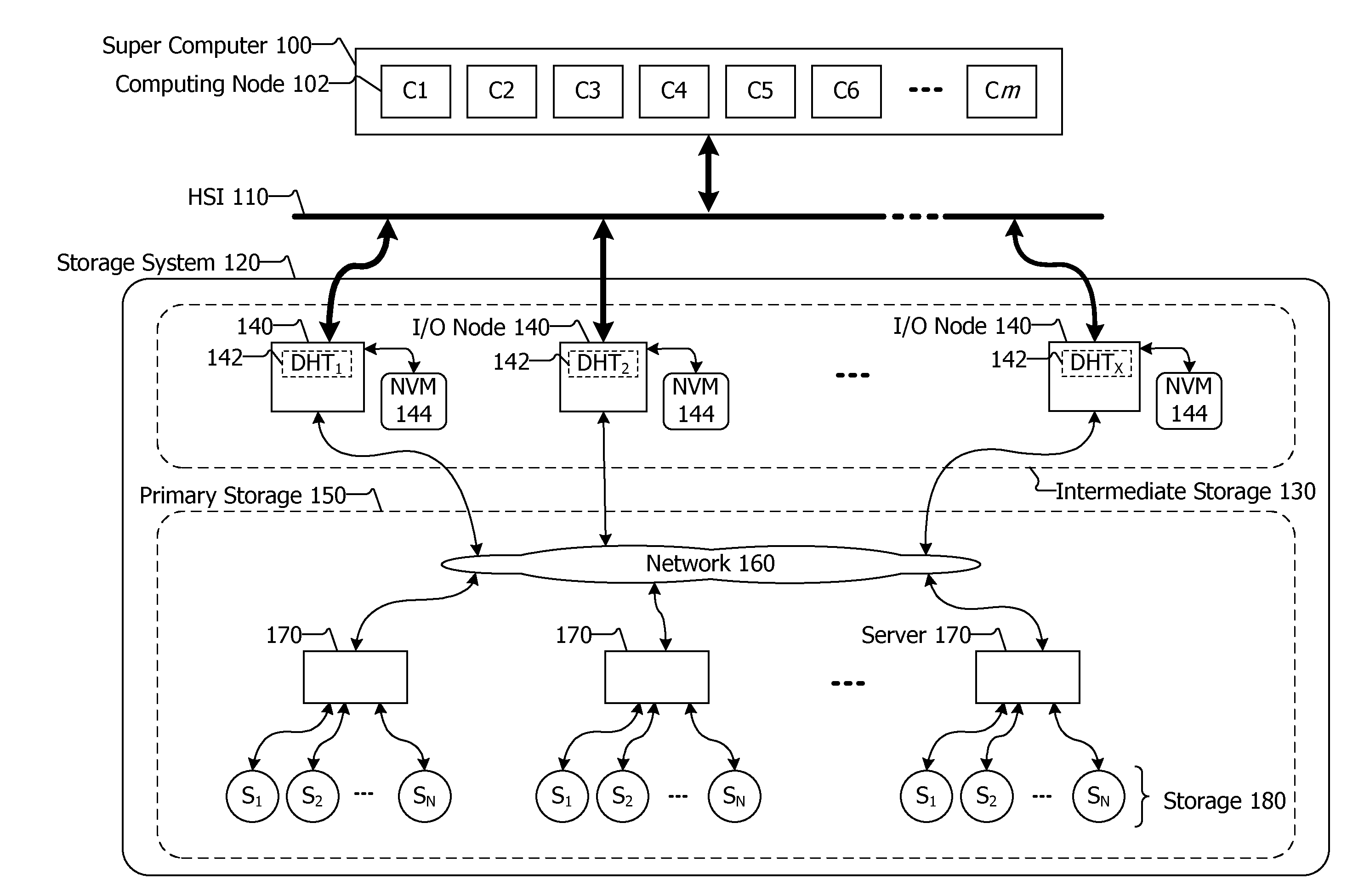
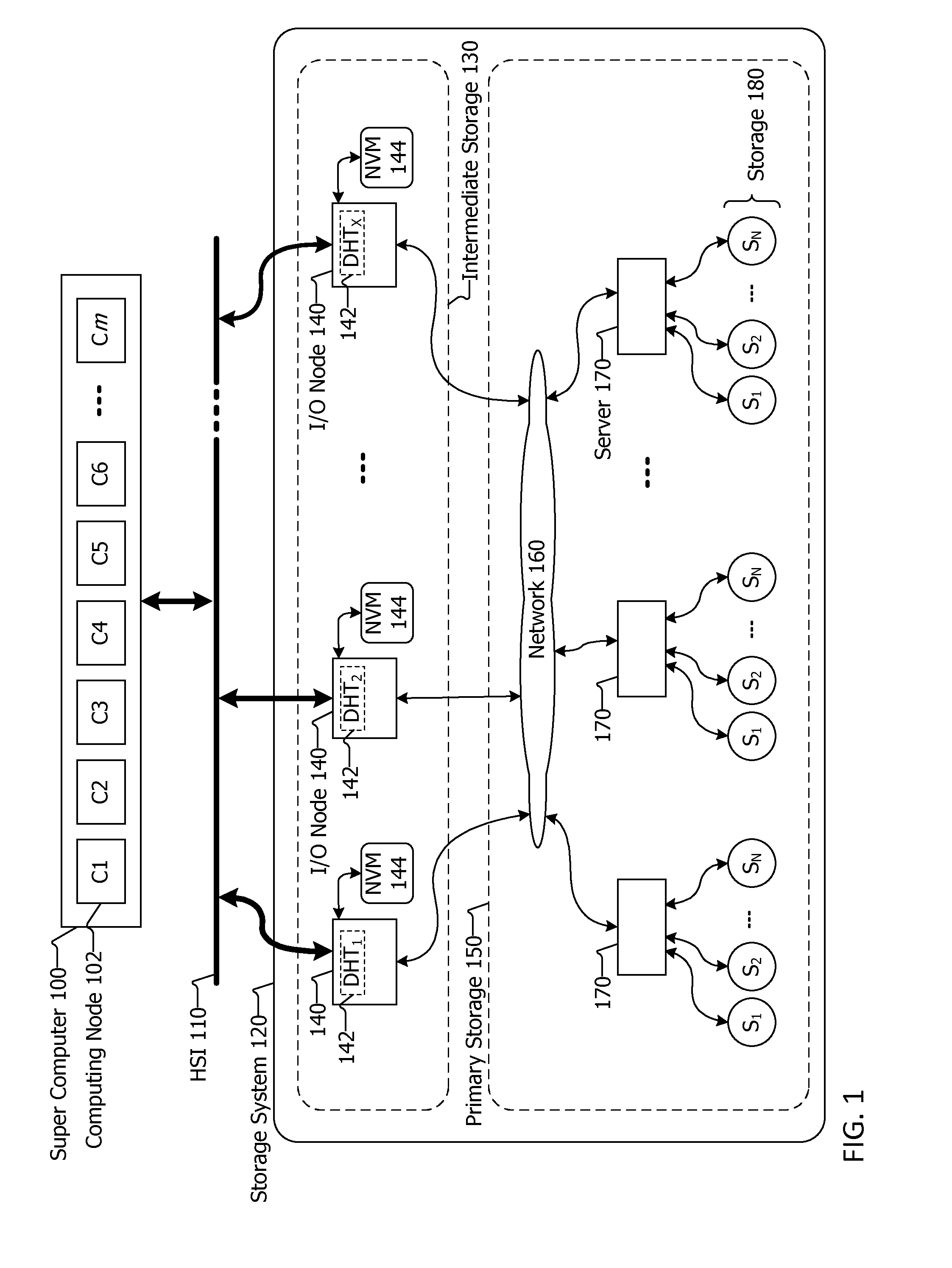
[0021]FIG. 1 is a block diagram of a data storage system 120 coupled with a super computer 100. The super computer 100 may be a compute cluster that includes a plurality of computing nodes 102. Similarly, the compute cluster may be a super computer. Each computing node has at least one core and may have multiple cores, such as 2, 4, 8, 32, etc. The computing nodes may be in one or more racks, shelves or cabinets, or combinations thereof. The super computer 100 is coupled via a High Speed Interconnect (HSI) 110 to the data storage system 120. The HSI 110 may conform to the INFINIBAND, CASCADE, GEMINI architecture or standard and their progeny, may be an optical fiber technology, may be proprietary, and the like. The data storage system 120 includes intermediate storage 130 and primary storage 150. The intermediate storage 130 includes a plurality of servers referred to as I / O node 140, each I / O node having a portion of a Distributed Hash Table (DHT) 142 included therein, and having N...

second embodiment

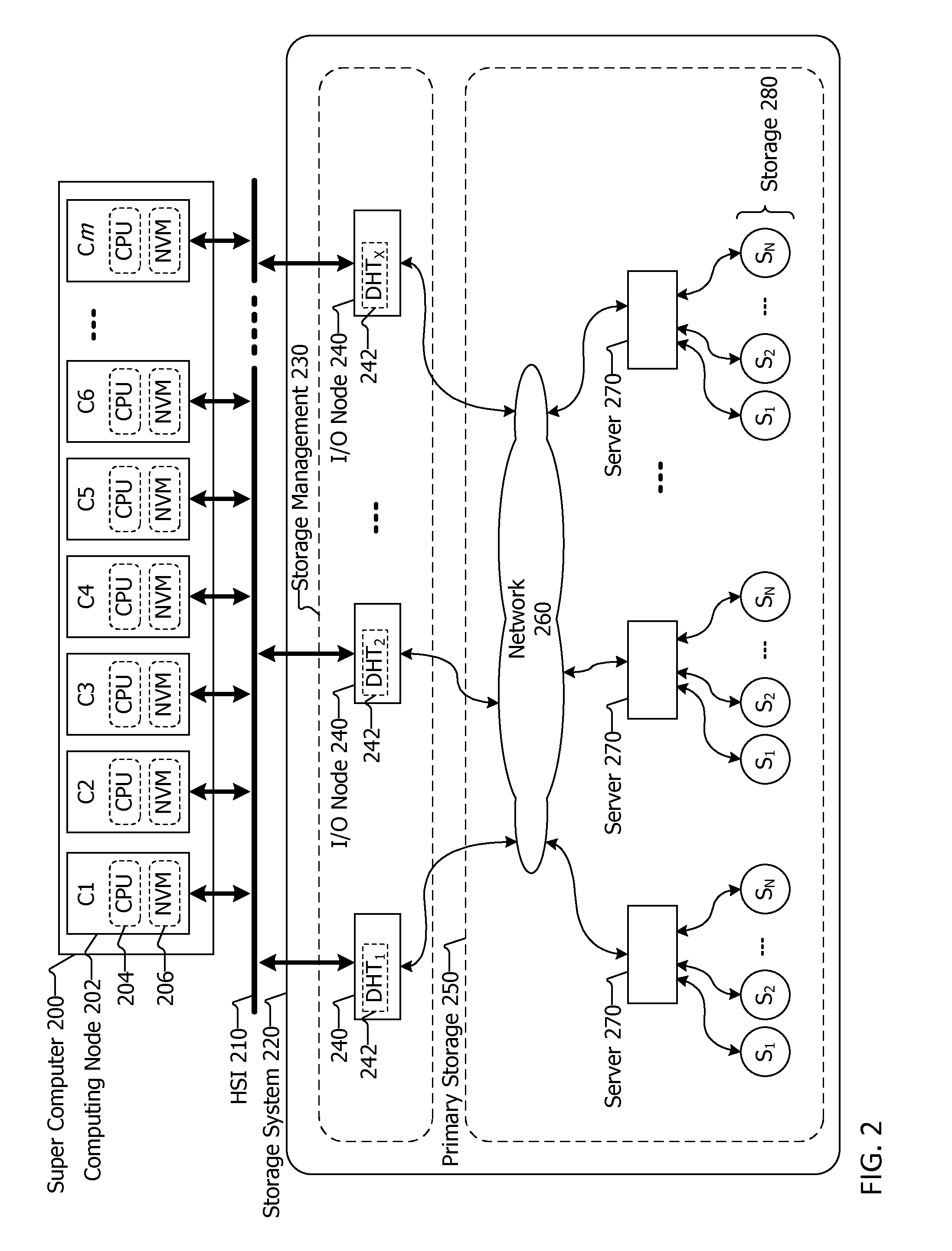
[0040]FIG. 2 is a block diagram of a data storage system coupled with a super computing system. In this embodiment, super computer 200 includes multiple computing nodes 202. Similarly, a group of computing nodes may form a compute cluster and the compute cluster may be a super computer. Each computing node includes a CPU 204 and its own NVM 206. The CPU may be single core have multiple cores. An advantage of this configuration is that the NVM is included in the computing nodes 202 to increase speed of access to the NVM 206 by the CPU 206 in the same computing node 202. In this configuration, the use of NVM, regardless of its location, is unbounded such that data from any of the CPUs may be stored to the NVM of another computing node. When data is to be written by a CPU in one computing node to the NVM of another computing node, the appropriate I / O node must be updated or notified about the computing node writing to the NVM of another computing node. This is because the I / O nodes 240...

third embodiment

[0042]FIG. 3 is a block diagram of a data storage system coupled with a super computing system. In this embodiment, the I / O nodes 310 are included in the super computer 300 or within or closely coupled with a compute cluster of computing nodes. This contrasts the other embodiments shown in FIGS. 1 and 2 in which the I / O nodes are included in a storage system coupled with the super computer. Further, the NVM 306 is included in the super computer 300 and is accessible to both computing nodes 302 and the I / O nodes 310 via a local interconnect 304. The local interconnect 304 may conform to the serial attached storage (SAS) standard, the peripheral component interconnect express or PCI Express standard, may implement a DRAM-like protocol or other data communication standard or technology. This configuration allows computing nodes 302 to access any available NVM 306. The use of the DHT 312 in the I / O nodes 310 allows for quick access to data items stored in the NVM 306 even as the computi...


PUM


Abstract

Data storage systems and methods for storing data are described herein. The storage system may be integrated with or coupled with a compute cluster or super computer having multiple computing nodes. A plurality of nonvolatile memory units may be included with computing nodes, coupled with computing nodes or coupled with input / output nodes. The input / output nodes may be included with the compute cluster or super computer, or coupled thereto. The nonvolatile memory units store data items provided by the computing nodes, and the input / output nodes maintain where the data items are stored in the nonvolatile memory units via a hash table distributed among the input / output nodes. The use of a distributed hash table allows for quick access to data items stored in the nonvolatile memory units even as the computing nodes are writing large amounts of data to the storage system quickly in bursts.

Description

RELATED APPLICATION INFORMATION[0001]This patent claims priority from provisional patent application No. 61 / 715,243 filed Oct. 17, 2012 which is incorporated by reference in its entirety.NOTICE OF COPYRIGHTS AND TRADE DRESS[0002]A portion of the disclosure of this patent document contains material which is subject to copyright protection. This patent document may show and / or describe matter which is or may become trade dress of the owner. The copyright and trade dress owner has no objection to the facsimile reproduction by anyone of the patent disclosure as it appears in the Patent and Trademark Office patent files or records, but otherwise reserves all copyright and trade dress rights whatsoever.BACKGROUND[0003]1. Field[0004]This disclosure relates to data stored in a data storage system and an improved architecture and method for storing data to and retrieving data from a data storage system particularly in a high speed super computing environment.[0005]2. Description of the Relat...

Claims


Application Information

Patent Timeline
Patent Type & Authority Applications(United States)
IPC IPC(8): G06F12/02
CPCG06F12/0246G06F12/0871G06F17/30067G06F17/30097G06F17/30194G06F16/182G06F13/4282G06F16/10G06F16/137G06F3/061G06F3/0655G06F3/0688
Inventor NOWOCZYNSKI, PAULCOPE, JASON MICAHMANNING, GORDONMOLARO, DONPISZCZEK, MICHAELUPPU, PAVAN
Owner DATADIRECT NETWORKS
Learn More