Reverse-flow annular combustor for reduced emissions

a combustor and annular technology, applied in the direction of machines/engines, efficient propulsion technologies, lighting and heating apparatus, etc., can solve the problems of flow interference with the stoichiometry of the rql combustion process, particularly difficult in the rql combustor, thermal stress and other problems, etc., to reduce the diameter of the combustion chamber, reduce the radial distance, and reduce the passage height of the combustion chamber

Active Publication Date: 2014-04-24
HONEYWELL INT INC
View PDF7 Cites 6 Cited by
  • Summary
  • Abstract
  • Description
  • Claims
  • Application Information

AI Technical Summary

Benefits of technology

[0007]In accordance with another exemplary embodiment, a reverse flow annular combustor for a gas turbine engine with an engine centerline is provided. The reverse flow annular combustor includes an inner liner; an outer liner circumscribing the inner liner; a combustor dome having a first edge coupled to the inner liner and a second edge coupled to the outer liner, the combustor dome forming a combustion chamber with the inner liner and the outer liner; and a fuel injector coupled to the outer liner and configured to inject a stream of fuel into the combustion chamber in a tangential direction relative to the engine centerline. The combustion chamber comprises a rich burn zone, a quench zone, and a lean burn zone to support combustion of air flow through the inner liner and the outer liner. The combustion chamber further comprises a convergent section located upstream of the quench zone and configured to decrease a passage height of the combustion chamber from the combustor dome to the quench zone.
[0008]In accordance with another exemplary embodiment, a combustor for a gas turbine engine is provided. The combustor includes an annular inner liner; an annular outer liner circumscribing the annular inner liner; and a combustor dome having a first edge coupled to the annular inner liner and a second edge coupled to the annular outer liner, the combustor dome forming a combustion chamber with the annular inner liner and the annular outer liner. The combustion chamber accommodates fluid flow through the annular inner and annular outer liners. The combustion chamber converges in the direction of the air flow to reduce a diameter of the combustion chamber. The combustor dome is configured to bifurcate the air flow at the combustor dome into a first stream directed to the annular inner liner and a second stream directed to the annular outer liner.
[0009]In accordance with another exemplary embodiment, a combustor for a gas turbine engine with an engine centerline is provided. The combustor includes an inner liner; an outer liner circumscribing the inner liner; a combustor dome having a first edge coupled to the inner liner and a second edge coupled to the outer liner, the combustor dome forming a combustion chamber with the inner liner and the outer liner; and a fuel injector coupled to the outer liner and configured to inject a stream of fuel into the combustion chamber in a tangential direction relative to the engine centerline. The combustion chamber comprises a primary zone and a secondary zone to support combustion of fuel and fluid flow through the inner liner and the outer liner. A passage height in the primary zone converges to reduce a radial distance between the inner liner and the outer liner.

Problems solved by technology

In addition to reducing emissions, combustor designers further attempt to manage the temperature characteristics of the combustion process, which is particularly difficult in an RQL combustor.
High temperatures may cause thermal stresses and other problems.
While increased cooling flows may improve cooling, such additional air flow may interfere with the stoichiometries of the RQL combustion process.

Method used


Image

  • Reverse-flow annular combustor for reduced emissions
  • Reverse-flow annular combustor for reduced emissions
  • Reverse-flow annular combustor for reduced emissions

Examples


Embodiment Construction

[0021]The following detailed description is merely exemplary in nature and is not intended to limit the invention or the application and uses of the invention. Furthermore, there is no intention to be bound by any theory presented in the preceding background or the following detailed description.

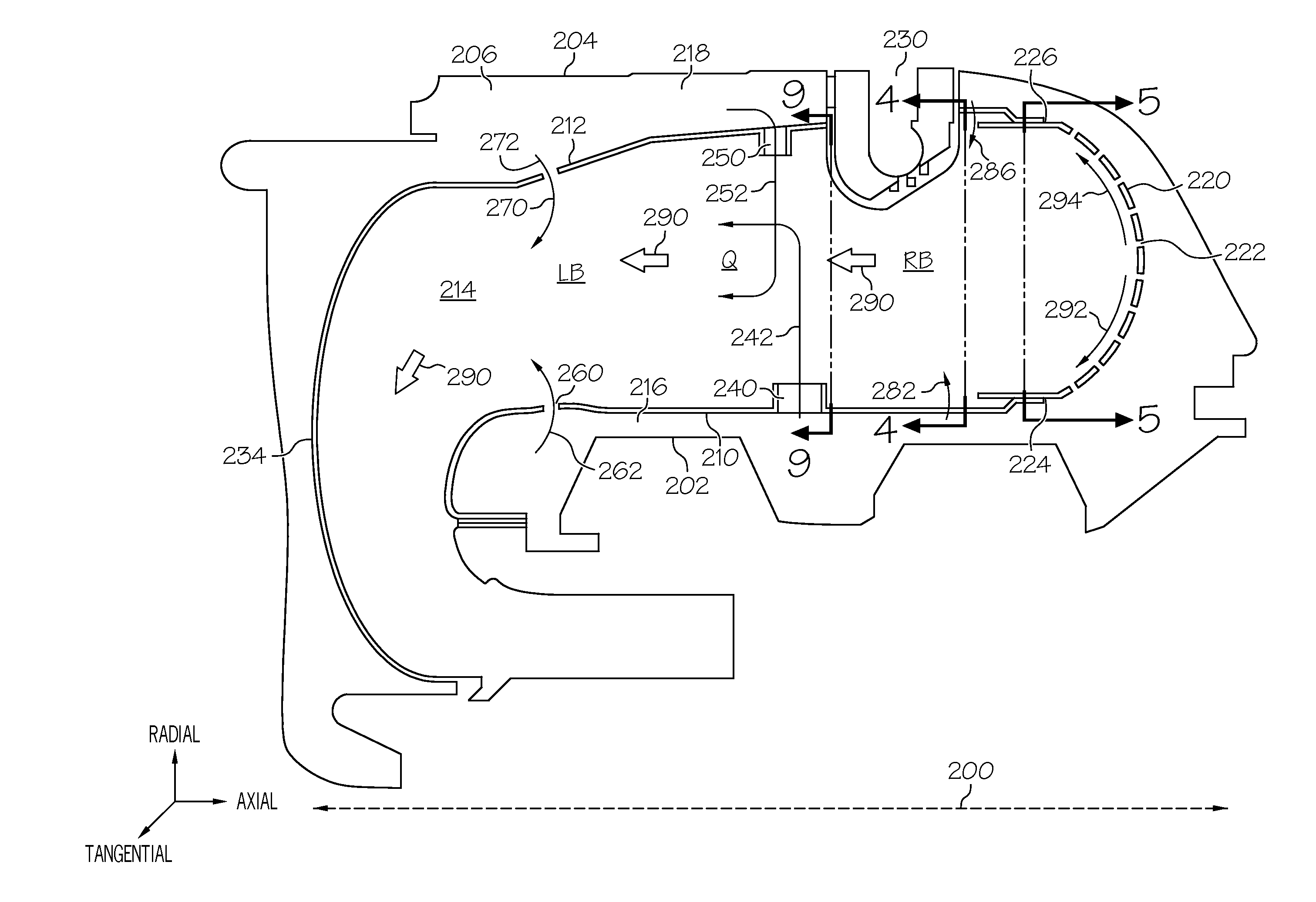
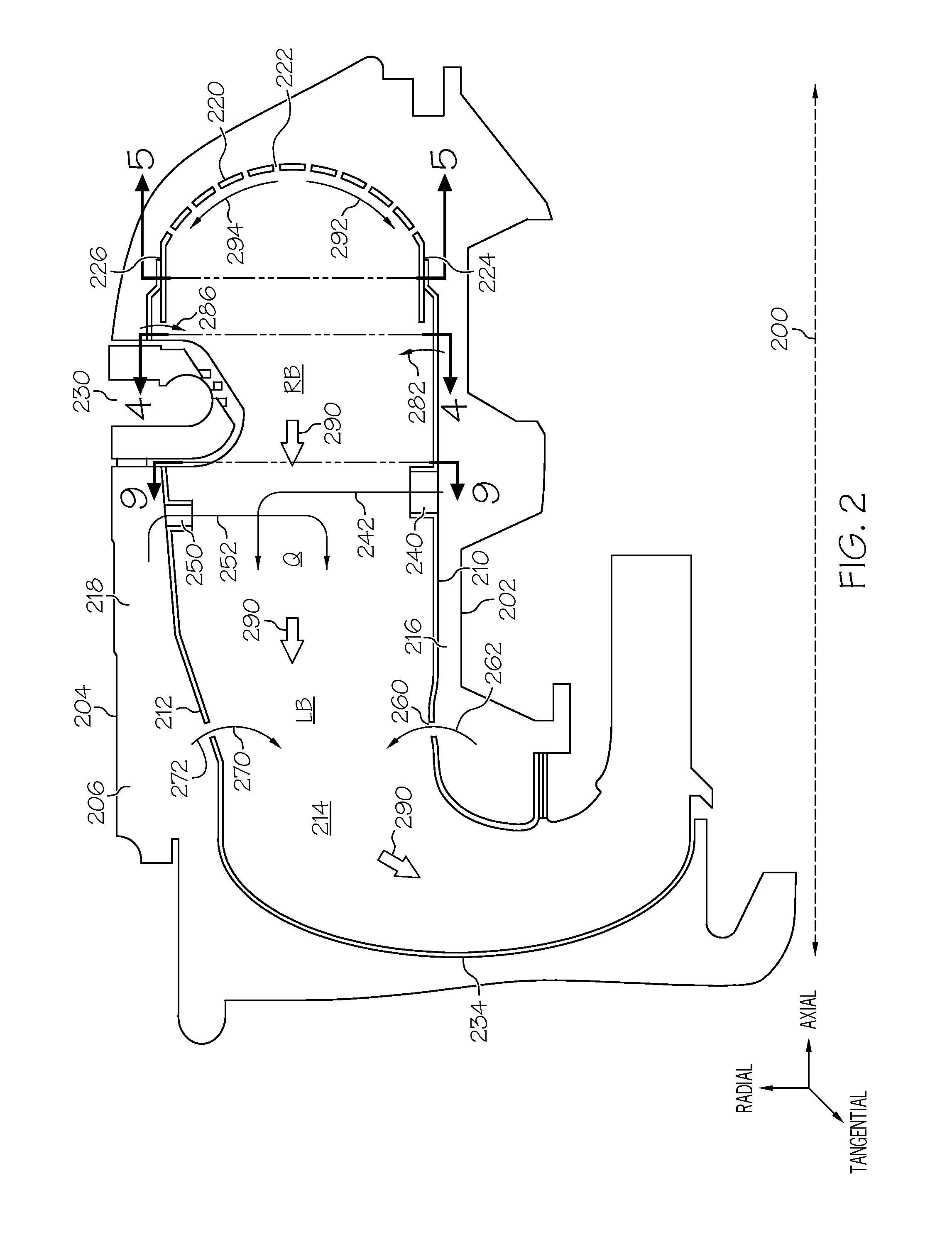
[0022]Broadly, the exemplary embodiments discussed herein provide a gas turbine engine with a rich burn, quick quench, lean burn (RQL) combustor having improved NOx emissions and temperature characteristics. Particularly, in one exemplary embodiment, the combustor includes a combustor dome configured to bifurcate the combustion gases into a first combustion stream towards the inner liner and a second combustion stream toward the outer liner. The combustor may further include a fuel injector that injects a substantially tangential stream of fuel into the combustion chamber; quench air admission holes that admit a set of interleaved, over-penetrating quench jets; and a row of dilution air admi...


PUM


Abstract

A combustor for a gas turbine engine is provided. The combustor includes an annular inner liner; an annular outer liner circumscribing the annular inner liner; and a combustor dome having a first edge coupled to the annular inner liner and a second edge coupled to the annular outer liner, the combustor dome forming a combustion chamber with the annular inner liner and the annular outer liner. The combustion chamber accommodates fluid flow through the annular inner and annular outer liners. The combustion chamber converges in the direction of the air flow to reduce a diameter of the combustion chamber. The combustor dome is configured to bifurcate the air flow at the combustor dome into a first stream directed to the annular inner liner and a second stream directed to the annular outer liner.

Description

TECHNICAL FIELD[0001]The present invention generally relates to gas turbine engines, and more particularly relates to rich burn, quick quench, lean burn (RQL) reverse-flow annular combustors for gas turbine engines that provide reduced emissions.BACKGROUND[0002]A gas turbine engine may be used to power aircraft or various other types of vehicles and systems. Such engines typically include a compressor that receives and compresses incoming gas such as air; a combustor in which the compressed gas is mixed with fuel and burned to produce high-pressure, high-velocity exhaust gas; and one or more turbines that extract energy from the exhaust gas exiting the combustor.[0003]There is an increasing desire to reduce gaseous pollutant emissions, particularly oxides of nitrogen (NOx), that form during the combustion process. One approach to reduce NOx emissions is the implementation of a rich burn, quick quench, lean burn (RQL) combustion concept. A combustor configured for RQL combustion incl...

Claims


Application Information

Patent Timeline
Patent Type & Authority Applications(United States)
IPC IPC(8): F23R3/06F23R3/54F23R3/26
CPCF23R3/002F23R3/06F23R3/16F23R3/54F23R2900/00015F23R2900/03041Y02T50/60
Inventor DUDEBOUT, RODOLPHEKUHN, TERRELKUCHANA, VINAYENDERHASTI, VEERARAGHAVA RAJUGAGE, RAYMONDJAMES, SUNIL
Owner HONEYWELL INT INC
Why Eureka
Try Eureka