Direct steam generation of boiler blowdown

a technology of direct steam and boiler, which is applied in the direction of steam generation using hot heat carriers, insulation, borehole/well accessories, etc., can solve the problems of limiting reuse as feedwater, blowdown presents a problem, and further expensive treatment or inefficient concentration

Inactive Publication Date: 2014-04-24
CONOCOPHILLIPS CO
View PDF9 Cites 16 Cited by
  • Summary
  • Abstract
  • Description
  • Claims
  • Application Information

AI Technical Summary

Problems solved by technology

Several treatment processes remove constituents which form harmful deposits in the boiler or steam generator but without even further costs do not remove all dissolved solids.
The blowdown presents a problem regardless of application requi

Method used


Image

  • Direct steam generation of boiler blowdown
  • Direct steam generation of boiler blowdown

Examples


Embodiment Construction

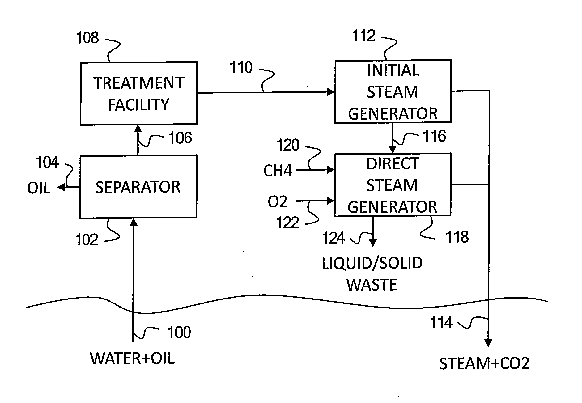
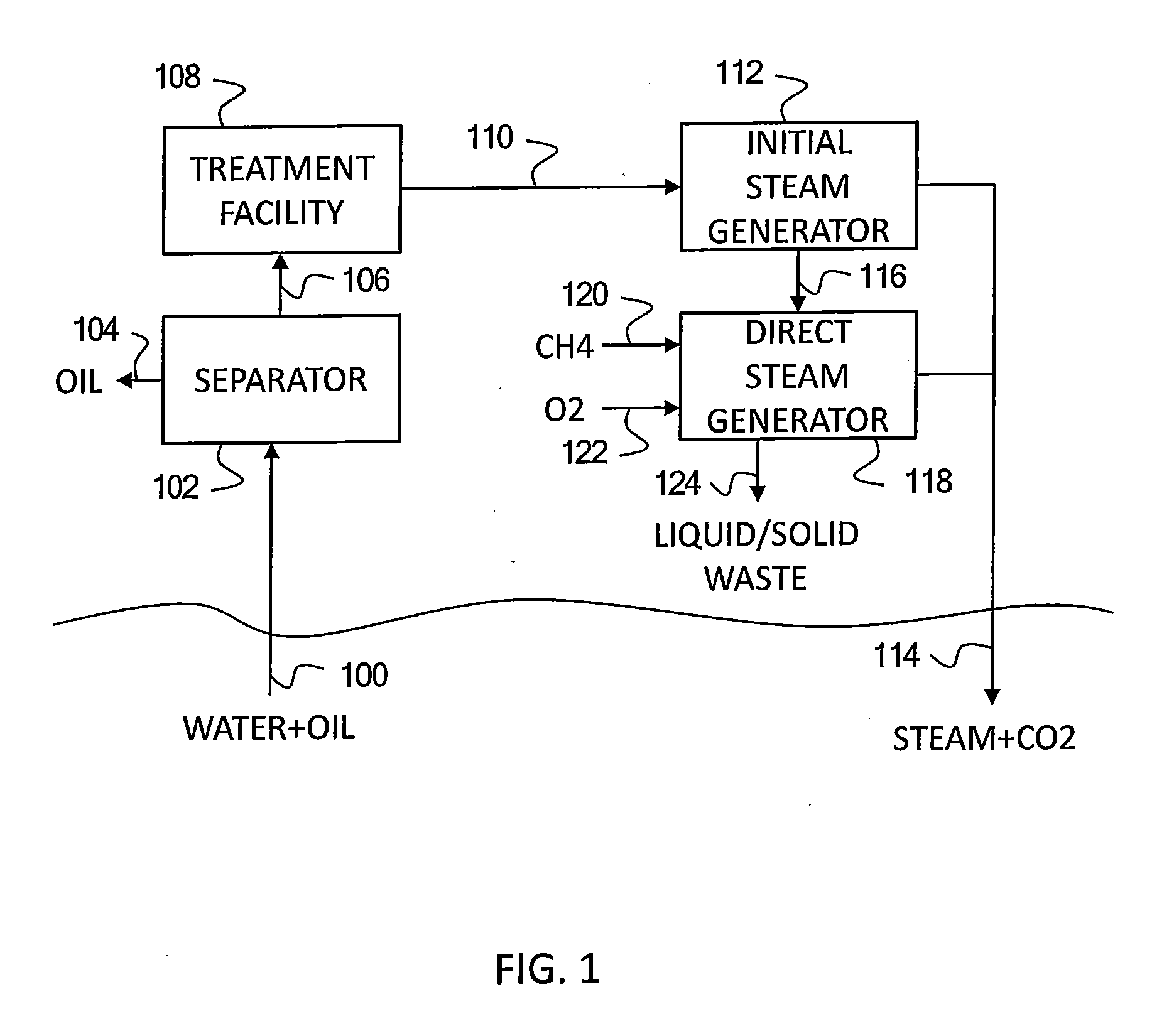
[0013]Embodiments of the invention relate to systems and methods of generating steam from produced water by passing the produced water through first and second steam generators coupled together. The first steam generator produces wet steam in which a liquid effluent with impurities of the produced water passes to the second steam generator. The second steam generator combusts fuel and oxidant in direct contact with the liquid effluent. The first and second steam generators limit fouling and waste while providing a combined steam output that may include combustion products from only the second steam generator.

[0014]FIG. 1 depicts a production well 100, a separator 102, a treatment facility 108, an initial steam generator 112, a direct steam generator 118 and an injection well 114 used in conjunction with heavy oil or bitumen extraction from a reservoir. During the extraction, steam injected into the reservoir through the injection well 114 increases the mobility of the sought after o...


PUM


Abstract

Systems and methods generate steam from produced water by passing the produced water through first and second steam generators coupled together. The first steam generator produces wet steam in which a liquid effluent with impurities of the produced water passes to the second steam generator. The second steam generator combusts fuel and oxidant in direct contact with the liquid effluent. The first and second steam generators limit fouling and waste while providing a combined steam output that may include combustion products from only the second steam generator.

Description

CROSS-REFERENCE TO RELATED APPLICATIONS[0001]This application is a non-provisional application which claims benefit under 35 USC §119(e) to U.S. Provisional Application Ser. No. 61 / 717,676 filed Oct. 24, 2012, entitled “DIRECT STEAM GENERATION OF BOILER BLOWDOWN,” which is incorporated herein in its entirety.STATEMENT REGARDING FEDERALLY SPONSORED RESEARCH OR DEVELOPMENT[0002]NoneFIELD OF THE INVENTION[0003]Embodiments of the invention relate to methods and systems of handling blowdown from initial steam generation with additional direct steam generation.BACKGROUND OF THE INVENTION[0004]Enhanced oil recovery processes employ thermal methods to improve recovery of heavy oils from subsurface reservoirs. For example, injection of steam into heavy oil bearing formations heats the oil in the reservoir, which reduces the viscosity of the oil and allows the oil to flow to a collection well. A mixture of the oil and produced water that flows to the collection well is recovered to the surfac...

Claims


Application Information

Patent Timeline
IPC IPC(8): F22B1/18F22B37/56F22B29/06E21B43/24E21B43/16
CPCF22B1/1853E21B43/164F22B37/56F22B29/06E21B43/2406F22B1/18Y02E20/34
Inventor LATIMER, EDWARD G.FIEDLER, MICHELLE R.
Owner CONOCOPHILLIPS CO
Why Eureka
Try Eureka