
Wind turbine fault detection circuit and method

a fault detection and wind turbine technology, applied in the direction of power supply testing, short-circuit testing, emergency control, etc., can solve the problems of inaccurate or reliable method of detecting ground faults, loss of power, and safety hazards, so as to reduce ground impedance and reliable measurement

Active Publication Date: 2014-04-24
VESTAS WIND SYST AS
View PDF8 Cites 12 Cited by
  • Summary
  • Abstract
  • Description
  • Claims
  • Application Information

AI Technical Summary

Benefits of technology

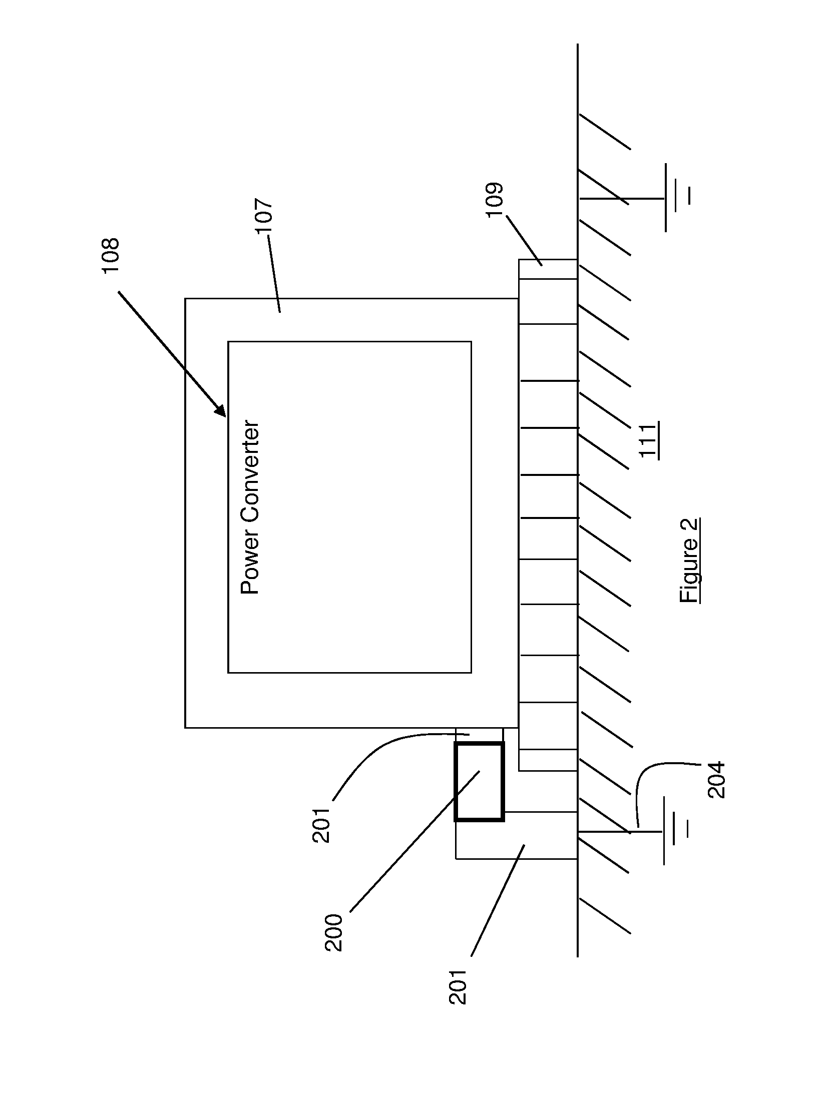
The patent describes a method to accurately measure the real ground current and identify fault conditions in a wind turbine. This is accomplished by using a magnetometer that can measure both the AC and DC components of the ground current. The magnetometer can be placed directly on a bus bar that connects the power converter to the ground element, or across a slot in the bus bar. The measurement is done by detecting the magnetic field created by the ground current flowing through the bus bar. The technical effect is a more reliable and accurate identification of fault conditions, which can prevent damage and improve the overall performance of wind turbines.

Problems solved by technology

It is known to use current sensors for power converter systems to determine presence of ground faults which may cause loss of power and create safety hazards.
If, on the other hand, there is a current leak in the power converter, a non-zero reading is recorded at the output of the power converter and this is an indication of a possible ground fault.
However, such a method of detecting ground faults may not be accurate or reliable due to noise created by converter switching that is coupled through a circuit breaker (CB).

Method used


Image

  • Wind turbine fault detection circuit and method
  • Wind turbine fault detection circuit and method
  • Wind turbine fault detection circuit and method

Examples


Embodiment Construction

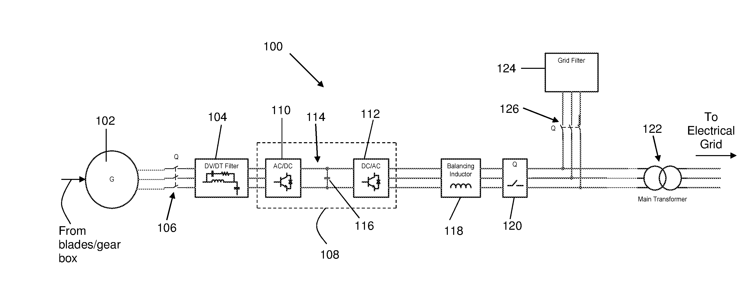
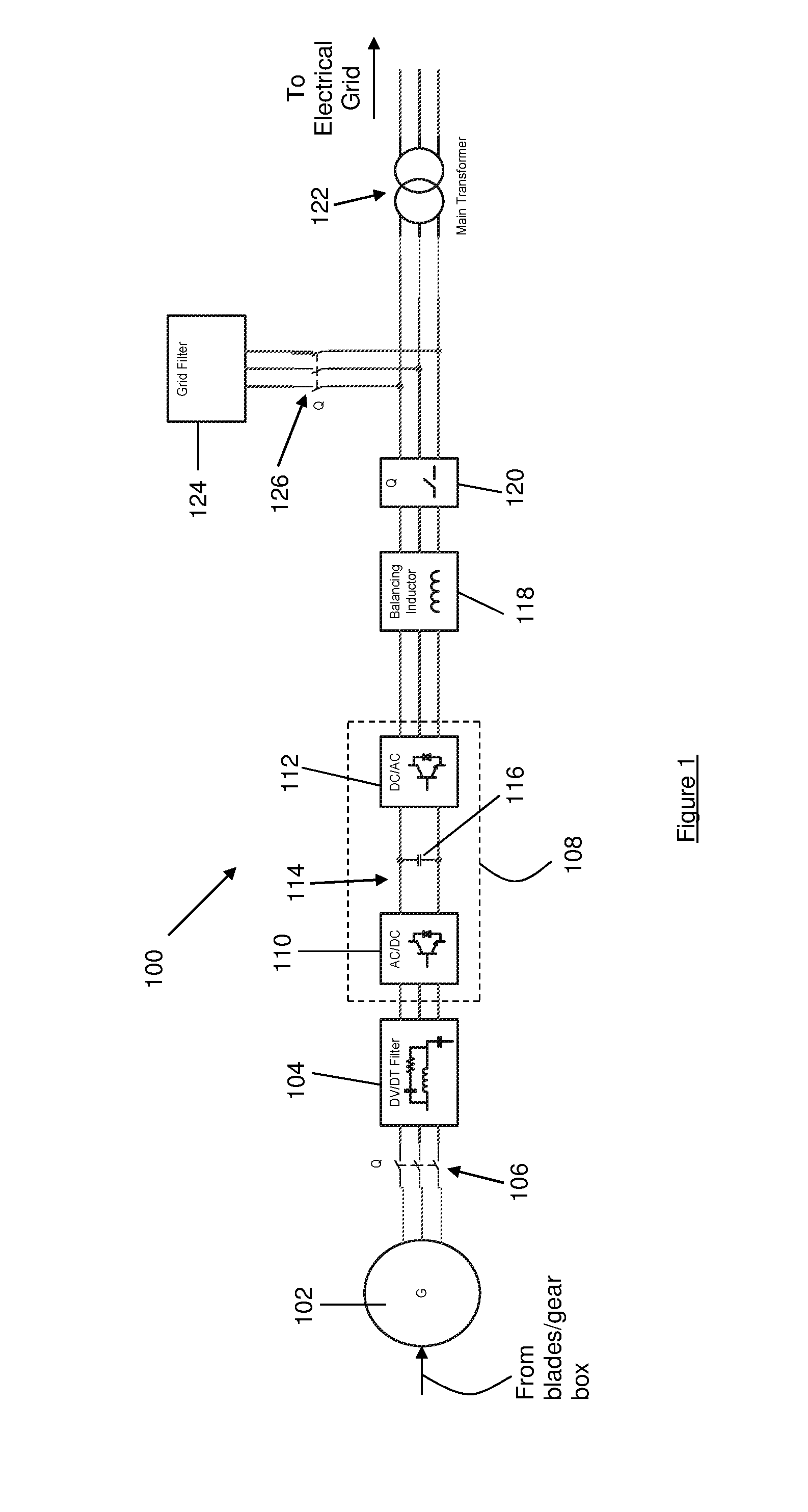
[0027]FIG. 1 is a block diagram showing an overview of an electrical system 100 of a wind turbine according to an embodiment of the invention. The electrical system 100 includes a generator 102 configured to convert mechanical energy from the turning of rotor blades (not shown) of the wind turbine to electrical energy. As it is understood, a gear box may be used to step up a low rotational speed of the rotor blades to a higher rotational speed suitable for operating the generator 102. The gear box may be omitted if the generator 102 is a multi-pole generator adapted to receive the low rotational speed of the rotor blades.

[0028]The generator 102 in this embodiment is a permanent magnet synchronous generator. As an alternative, the generator may be a singly or doubly-fed synchronous generator, an induction generator or any other type of generator comprising a stator winding. Typically, the electrical system 100 is provided in a nacelle (not shown) of the wind turbine.

[0029]The electri...


PUM


Abstract

A wind turbine fault detection circuit and method is disclosed herein. In a described embodiment, the wind turbine fault detection circuit comprises a magnetometer in the form of a hall-effect sensor coupled between a power converter and a ground element of the power converter and configured to measure a ground current from the power converter to obtain a real ground current Ig; and a comparator configured to determine presence of a fault based on the real ground current.

Description

BACKGROUND AND FIELD OF THE INVENTION[0001]The invention relates to a wind turbine fault detection circuit and method.[0002]It is known to use current sensors for power converter systems to determine presence of ground faults which may cause loss of power and create safety hazards. A common approach of detecting ground faults of a three-phase power converter is to sum current outputs of the power converter. A desired result would be when the output currents are balanced, i.e. the output currents are 120° out of phase with each other and of equal magnitude, and the output currents cancel each other to result in a summed current value of zero. If, on the other hand, there is a current leak in the power converter, a non-zero reading is recorded at the output of the power converter and this is an indication of a possible ground fault.[0003]However, such a method of detecting ground faults may not be accurate or reliable due to noise created by converter switching that is coupled through...

Claims


Application Information

Patent Timeline
Patent Type & Authority Applications(United States)
IPC IPC(8): G01R31/02H02H7/12H02H3/16
CPCG01R31/025H02H7/1216H02H3/16F05B2220/7064F05B2260/80F05B2270/107G01R31/42H02H7/06F03D17/00F03D9/255H02H3/165Y02E10/72G01R31/52
Inventor PARKHOU, MASOUDLUO, XUE WENTUMABCAO, MICHAEL CASEM
Owner VESTAS WIND SYST AS
Learn More