
Path loss calculation method, path loss calculation device, path loss calculation program, wireless communication system, and spectrum manager

Active Publication Date: 2014-04-24
NEC CORP
View PDF4 Cites 16 Cited by
  • Summary
  • Abstract
  • Description
  • Claims
  • Application Information

AI Technical Summary

Benefits of technology

The present invention provides a method for estimating the path loss value of a primary receiving station and using it to correct the reception power of a secondary signal measured at another frequency. This allows for accurate measurement of the secondary signal even in environments where the primary reception power is small. By correcting the path loss estimate, the margin necessary for suppression of the permissible transmission power can be reduced, resulting in a higher permissible transmission power.

Problems solved by technology

However, since the path loss estimation includes an error caused by shadowing, an error caused by a difference between a propagation model (a path estimation formula such as the Okumura-Hata formula) and a real environment, or the like, a CIR estimation error occurs consequently.
In the case of the technique disclosed in Patent Document 1, similarly to the technique disclosed in Non-Patent Document 1, since an error caused due to a difference with a real environment is included, a CIR estimation error occurs consequently.

Method used


Image

  • Path loss calculation method, path loss calculation device, path loss calculation program, wireless communication system, and spectrum manager
  • Path loss calculation method, path loss calculation device, path loss calculation program, wireless communication system, and spectrum manager
  • Path loss calculation method, path loss calculation device, path loss calculation program, wireless communication system, and spectrum manager

Examples


first embodiment

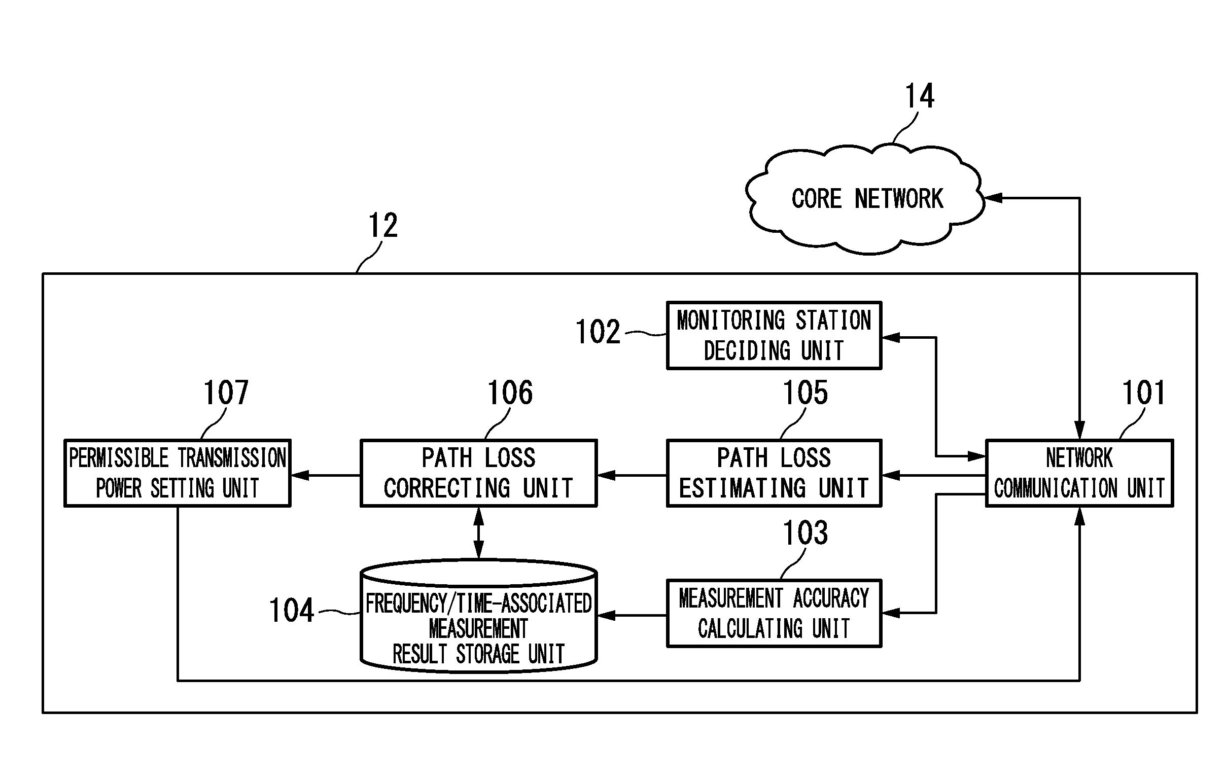
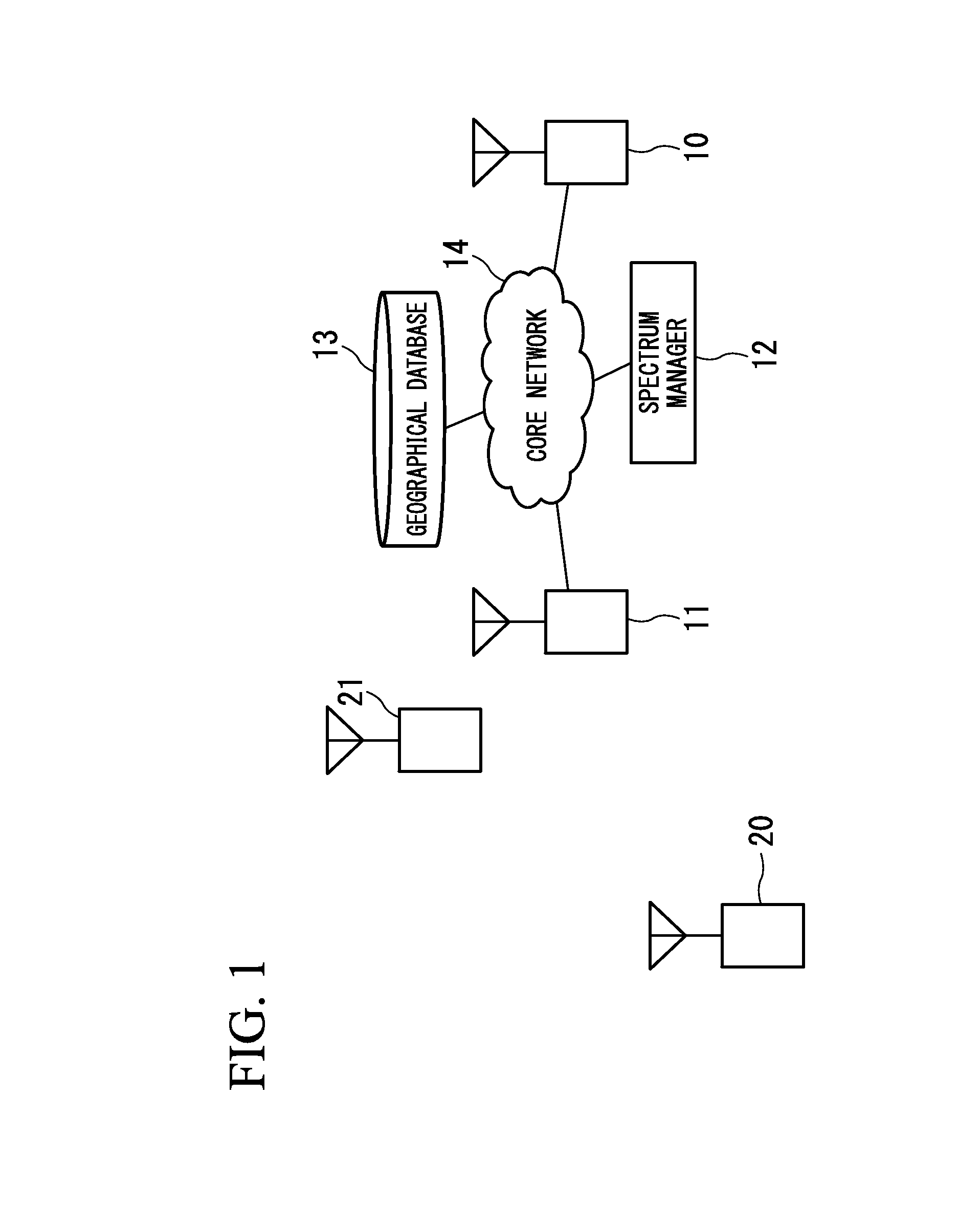
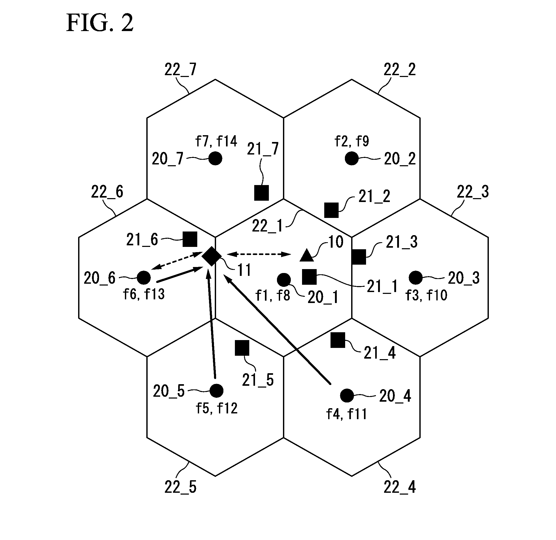
[0033]FIG. 1 is a system constitution diagram illustrating an exemplary cognitive radio system according to a first frequency of the present invention. The cognitive radio system performs communication as a secondary system by sharing a frequency with a primary system. In the following description, the primary system is assumed to be a television broadcast system, and the secondary system is assumed to be a cellular system. Of course, this constitution is merely an example, and a combination of the primary system and the secondary system is not limited to such a constitution. Examples of the combination of the primary system and the secondary system include a combination of a television system and a wireless regional access network (WRAN) system and a television system and a wireless regional system or disaster prevention radio communication of a self-governing community or the like. In these examples, the primary system may be a wireless microphone or a radio for specific use (for ...

second embodiment

[0177]In a second embodiment of the present invention, measurement accuracy information used for correction of the path loss estimation value is different from that in the first embodiment, and the ratio of a reception signal power estimation value of a measurement target to a reception power estimation value of other signals is used as the measurement accuracy information. For clear description, only different points from the first embodiment will be described.

[0178]In the first embodiment of the present invention, an interference to carrier ratio (ICR) which is the ratio of the reception power estimation value of the secondary signal and the reception power estimation value of the primary signal calculated based on the path loss estimation is used as the measurement accuracy information of the reception power measurement value of the secondary signal. Meanwhile, a CIR estimation value which is the ratio of the reception power estimation value of the primary signal and the receptio...


PUM


Abstract

A spectrum manager manages a secondary system that shares a frequency with a primary system. A communication unit receives a measurement value of reception power of a signal of the secondary system which is measured by a monitoring station, and holds the measurement value in a measurement result storage unit. A path loss estimating unit estimates a path loss at a first frequency, and a path loss correcting unit performs actual measurement correction on a path loss estimation value using one of a reception power measurement value of a radio signal of a secondary transmitting station measured at a second frequency different from the first frequency and a reception power measurement value of the radio signal of the secondary transmitting station measured in a period of time which is not used by the primary system. A permissible transmission power setting unit calculates permissible transmission power of the secondary transmitting station using the path loss estimation value which has been actually measured and corrected.

Description

TECHNICAL FIELD[0001]The present invention relates to a path loss calculation method, a path loss calculation device, and a path loss calculation program which calculate a propagation loss between radio stations, and a wireless communication system and a spectrum manager which perform power control using a path loss value.BACKGROUND ART[0002]A cognitive radio of recognizing an ambient wireless environment and optimizes communication parameters according to the wireless environment has been known. As an example of a cognitive radio, for example, there are cases in which a secondary system (interfering system) shares a frequency band allocated to a primary system (interfered system).[0003]When the secondary system shares the frequency band with the primary system, the secondary system does not have to influence existing services provided by the primary system. To this end, a transmitting station (hereinafter referred to as a “secondary transmitting station”) of the secondary system pe...

Claims


Application Information

Patent Timeline
IPC IPC(8): H04W24/02H04W24/08H04W52/24
CPCH04W24/02H04W52/242H04W24/08H04W16/14H04W16/18
Inventor MURAOKA, KAZUSHI
Owner NEC CORP
Features
  • Generate Ideas
  • Intellectual Property
  • Life Sciences
  • Materials
  • Tech Scout
  • Unparalleled Data Quality
  • Higher Quality Content
  • 60% Fewer Hallucinations
Learn More