Alignment devices and methods

a technology of alignment devices and balancing devices, applied in the field of joint alignment and balancing devices and methods for arthroplasty implants, can solve the problems of poor alignment of orthopedic implants relative, early wear and revision of orthopedic implants, and many of these machines and instruments are expensive and have not been readily adopted

Active Publication Date: 2014-04-24
SMITH & NEPHEW INC
View PDF5 Cites 29 Cited by
  • Summary
  • Abstract
  • Description
  • Claims
  • Application Information

AI Technical Summary

Benefits of technology

[0006]Another embodiment of the invention is a method of manufacturing a femoral implant alignment guide configured to be used with a particular patient. The embodiment includes evaluating one or more images of the patient's anatomy that include the patient's hip and the patient's knee and defining an axis from between the patient's femoral condyles through the patient's hip center. The method may also include forming a patient-matched body that includes an elongated resection slot that when placed against the patient's femoral condyles includes a major axis that is substantially perpendicular to the axis from between the patient's femoral condyles through the patient's hip center.
[0007]Still another embodiment of the invention is a method of implanting an arthroplasty device that includes providing a first instrument for aligning a first component of the arthroplasty device, wherein the first instrument includes an offset portion that is configured to extend to a physiological reference point that provides an alignment reference for placement of the first component. The method may also include aligning the first instrument with two or more physiological reference points and removing tissue adjacent to the first instrument to prepare a location to receive the first component. The method may also include providing a second instrument for aligning a second component of the arthroplasty device, wherein the second instrument includes an interface configured to couple with the location prepared to receive the first component, and aligning the second instrument with the location prepared to receive the first component. The method may include positioning tissue adjacent to the second instrument such that tissue adjacent to the first instrument is positioned appropriately relative to the tissue adjacent to the second instrument, removing tissue adjacent to the second instrument to prepare a location to receive the second component, implanting the first component of the arthroplasty device, and implanting the second component of the arthroplasty device.
[0008]Another embodiment of the invention is a method of implanting a knee arthroplasty device in a patient that includes provision of a femoral implant alignment guide for implanting a femoral component of the knee arthroplasty device in a patient comprising a body configured to be placed on a distal end of a femur and define an axis from between the patient's femoral condyles through the patient's hip center. The body may include an elongated resection slot with a major axis that is substantially perpendicular to the axis directed through the patient's hip center when the body is aligned on the axis through the patient's hip center, and an offset portion that is configured to extend to a point in a coronal plane of the patient that is shared with the patient's greater trochanter wherein the point is directly lateral of the patient's greater trochanter and wherein the offset portion is coupled to the body such that the body and the offset portion are substantially constrained from rotational displacement in a sagittal plane of the patient. The method may also include aligning the femoral implant alignment guide with two or more physiological reference points and removing at least a portion of the femoral condyles along a plane defined by the elongated resection slot. The method also includes provision of a tibial implant alignment guide for aligning a tibial component of the knee arthroplasty device, wherein the tibial implant alignment guide includes an interface configured to couple with the patient's femur. The method may also include aligning and coupling the tibial implant alignment guide with the patient's femur, positioning the patient's tibia appropriately relative to the patient's femur and coupling the tibial implant alignment guide to the patient's tibia, removing at least a portion of the patient's tibia in a configuration to receive a tibial component of the knee arthroplasty device, implanting a femoral component of the knee arthroplasty device, and implanting a tibial component of the knee arthroplasty device.
[0009]Yet another embodiment of the invention is a method of implanting a knee arthroplasty device in a patient that may include imaging at least the patient's femur and proximal tibia, defining an axis on one or more images from between the patient's femoral condyles through the patient's hip center, and sizing a femoral implant alignment guide based on images of the patient's femur such that an elongated resection slot in the femoral implant alignment guide has a major axis substantially perpendicular to the axis between the patient's femoral condyles and the patient's hip center when the femoral implant alignment guide is placed against the patient's femoral condyles. The method may also include aligning an offset portion of the femoral implant alignment guide with a point in a coronal plane of the patient that is shared with the patient's greater trochanter, wherein the point is directly lateral of the patient's greater trochanter, and aligning the femoral implant alignment guide with one or more physiological reference points on the distal femur. The method may include removing at least a portion of the femoral condyles along a plane defined by the elongated resection slot, coupling a tibial implant alignment guide to the patient's femur at least in part where at least a portion of the femoral condyles were removed, positioning the patient's tibia appropriately relative to the patient's femur and coupling the tibial implant alignment guide to the patient's tibia, and removing at least a portion of the patient's tibia in a configuration to receive a tibial component of the knee arthroplasty device. The method may also include implanting a femoral component of the knee arthroplasty device and a tibial component of the knee arthroplasty device.
[0010]An additional embodiment of the invention is a method of providing information useful for implanting an orthopedic implant that includes providing a patient-matched instrument that includes a sensor for measuring force applied to the patient-matched instrument, placing the patient-matched instrument between two or more of: orthopedic instruments, orthopedic implant components, and bones, and reading forces and / or locations of forces applied during the alignment of two or more orthopedic instruments, orthopedic implant components, and bones. The method may also include the re-zeroing of the force sensor output in a particular patient-specific loading condition, altering the shapes or alignment of one or more orthopedic instruments, implant components and bones or other tissue, evaluating the change in the force sensor output, accepting the measured force delta or altering one or more of the orthopedic instrument, orthopedic implant components, and bones or other tissue to alter the measured force delta.
[0011]An additional embodiment of the invention is the representation of all pre-op plan information used to design the PM instrument and predict alignment outcomes within the context of one or more pre-operative radiographs. This radiographic preoperative plan is also used as a verification tool when overlaid over or otherwise compared with the postoperative radiograph.

Problems solved by technology

A common source of early wear and revision of orthopedic implants is improper alignment of the orthopedic implants relative to the natural physiology of the patient.
However, many of these machines and instruments are expensive and have not been readily adopted.
The CAS machines and software, as well as maintenance, can be a significant capital expenses to healthcare providers, which may or may not be reimbursed.
Also, pre-operative three-dimensional models are not always particularly useful to a surgeon where the surgeon is more likely to have only x-ray (radiograph) equipment available to assist with evaluation of the surgery.
MRI scans or CT scans simply often may not be available.
The volume and format of information provided by some of the more sophisticated tools may, in fact, have a negative effect on surgical efficiency and efficacy.
However, penetration of the medullary canal can lead to some complications, and avoiding the practice may benefit some patients.

Method used


Image

  • Alignment devices and methods
  • Alignment devices and methods
  • Alignment devices and methods

Examples


Embodiment Construction

[0047]The following descriptions of the depicted embodiments are merely exemplary in nature and are in no way intended to limit the invention, its application, or uses.

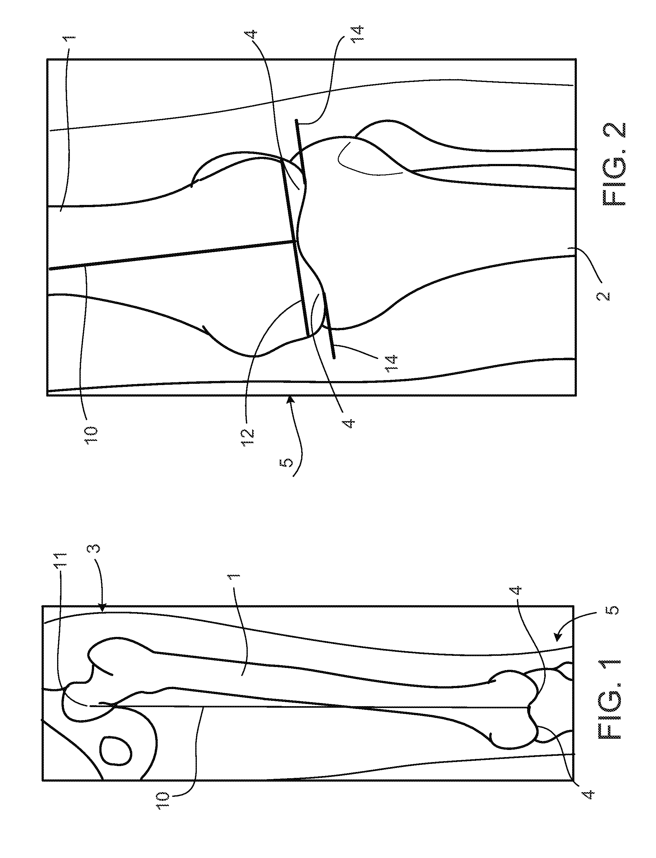
[0048]An anterior to posterior radiograph of a patient's femur 1, hip 3, and knee 5 is shown in FIG. 1. FIG. 2 shows the patient's femur 1, knee 5, and tibia 2. The images provided in FIGS. 1 and 2 are radiograph images produced with x-rays. In some embodiments, other imaging techniques and devices may be used, but in this embodiment, radiograph images are used to capture preoperative information for the manufacture of an alignment guide and for comparison with postoperative alignment information. An axis 10 is illustrated in FIGS. 1 and 2 that passes between the patient's femoral condyles 4 and through the patient's hip center 11 (FIG. 1). This axis 10 is well-known to approximate an appropriate alignment for a knee arthroplasty device. An axis 12 is illustrated in FIG. 2 that is substantially perpendicular to the ax...


PUM

PropertyMeasurementUnit
thicknessaaaaaaaaaa
rotational displacementaaaaaaaaaa
forceaaaaaaaaaa

Abstract

Embodiments of the invention include devices and methods for implanting arthroplasty devices. Some embodiments include designs that allow for use of x-ray images as the only images used to fully and accurately preoperatively and intraoperatively size and align arthroplasty device components and prepare all necessary tissue.

Description

CROSS-REFERENCE TO RELATED APPLICATION[0001]This application claims priority to and the full benefit of U.S. Provisional Patent Application No. 61 / 715,631, filed Oct. 18, 2012. The entirety of U.S. Provisional Patent Application No. 61 / 715,631 is incorporated by reference herein.BACKGROUND OF THE INVENTION[0002]The present invention relates generally to the installation of orthopedic implants with respect to patient physiology and function, and particularly to joint alignment and balancing devices and methods for arthroplasty implants.[0003]A common source of early wear and revision of orthopedic implants is improper alignment of the orthopedic implants relative to the natural physiology of the patient. Over the years, many sophisticated machines and instruments have been tried to improve alignment of orthopedic implants. However, many of these machines and instruments are expensive and have not been readily adopted. For example, computer assisted surgery (“CAS”) provides highly acc...

Claims


Application Information

Patent Timeline
Patent Type & Authority Applications(United States)
IPC IPC(8): A61B17/17A61F2/46A61F2/38
CPCA61B17/1764A61F2/4657A61F2/389A61F2/3859A61B17/155A61B2017/568A61F2/4684A61F2002/4658A61F2002/4668A61B2034/101A61B34/10A61B2034/108Y10T29/49A61B17/1703A61B17/175A61B2017/00526
Inventor WILKINSON, ZACHARY CHRISTOPHER
Owner SMITH & NEPHEW INC
Why Eureka
Try Eureka