Adhesive dispensing system and method using smart melt heater control

a technology of smart melt and heater control, which is applied in the direction of transportation and packaging, pipe heating/cooling, and level indicators by physical variable measurement, can solve the problems of limited change in temperature of adhesive at the heater unit caused by the reduction of the temperature of the heater unit, and achieves a short warm-up time, reduces the degradation rate of adhesive, and minimizes the effect of outgassing

Active Publication Date: 2014-05-01
NORDSON CORP
View PDF15 Cites 11 Cited by
  • Summary
  • Abstract
  • Description
  • Claims
  • Application Information

AI Technical Summary

Benefits of technology

[0009]In one aspect, the method also includes increasing the temperature of the heater unit back to the unit set point temperature when the fill system is actuated. A timer may be reset upon this actuation of the fill system, and this timer is used to determine whether the first set threshold time has been exceeded since the most recent supply of adhesive. As a result, long periods of relative inactivity or low throughput will automatically cause a cooling of the adhesive, which lowers the degradation rate of the adhesive and minimizes outgassing at an adhesive / air interface within the adhesive dispensing system.
[0010]The adhesive dispensing system may also include a reservoir configured to receive heated adhesive from the heater unit, the reservoir including a heating device. In these circumstances, the method may also include operating the heating device to maintain a reservoir set point temperature that maintains the temperature of adhesive within the reservoir, both before and after the first set threshold time has elapsed. As a result, the change in temperature of adhesive at the heater unit caused by the reduction in temperature of the heater unit is limited (such as to about 10° C.), which enables a shorter warm-up time from this smart melt state. To this end, the warm-up time for the heater unit may be so short that dispensing operations proceed immediately without delay when the heater unit is returned from the smart melt state.
[0011]Alternatively, the timer may be used to determine whether a second set threshold time has elapsed following the most recent actuation of the fill system. When the second set threshold time has elapsed, the temperature of the reservoir could also be reduced while continuing to operate the heating device, and this increases the change in temperature of the adhesive in the adhesive dispensing system to further reduce degradation of the adhesive. For example, the overall temperature change of adhesive may be an additional 5° C. in such an arrangement. The reduction of the temperature at the reservoir may be offset in time from the reduction of temperature at the heater unit to provide a staged reduction in temperature of the adhesive. The reduction in temperature at the heater unit may also be cycled periodically to preemptively warm adhesive back up before a new supply of adhesive is actuated at the fill system.

Problems solved by technology

As a result, the change in temperature of adhesive at the heater unit caused by the reduction in temperature of the heater unit is limited (such as to about 10° C.

Method used


Image

  • Adhesive dispensing system and method using smart melt heater control
  • Adhesive dispensing system and method using smart melt heater control
  • Adhesive dispensing system and method using smart melt heater control

Examples


Embodiment Construction

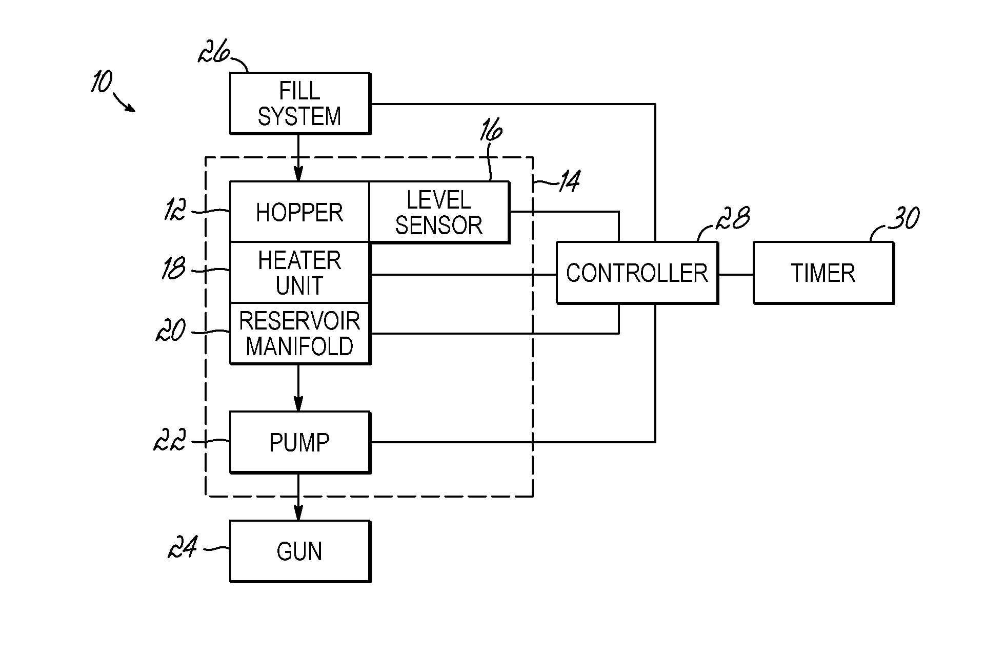
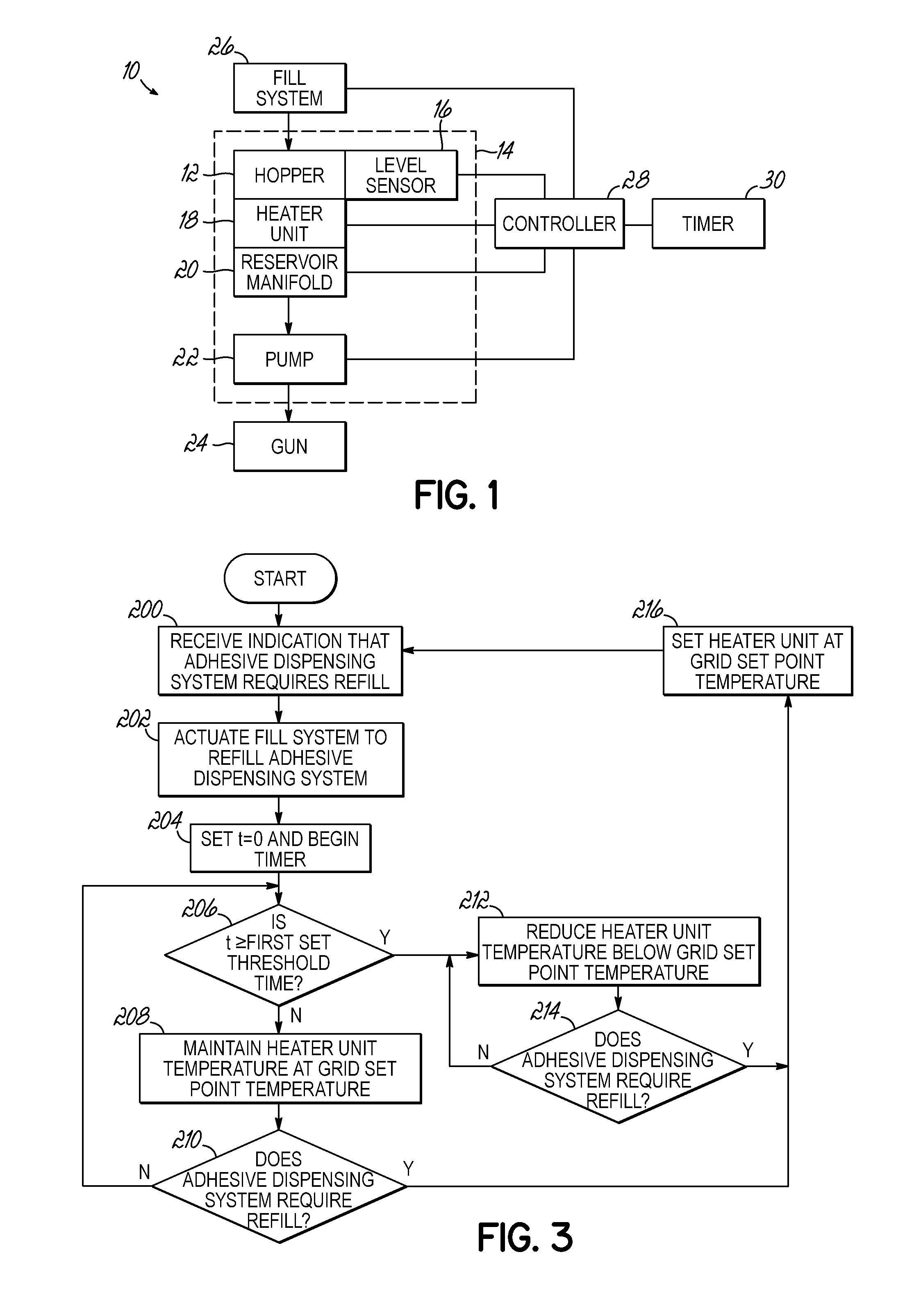
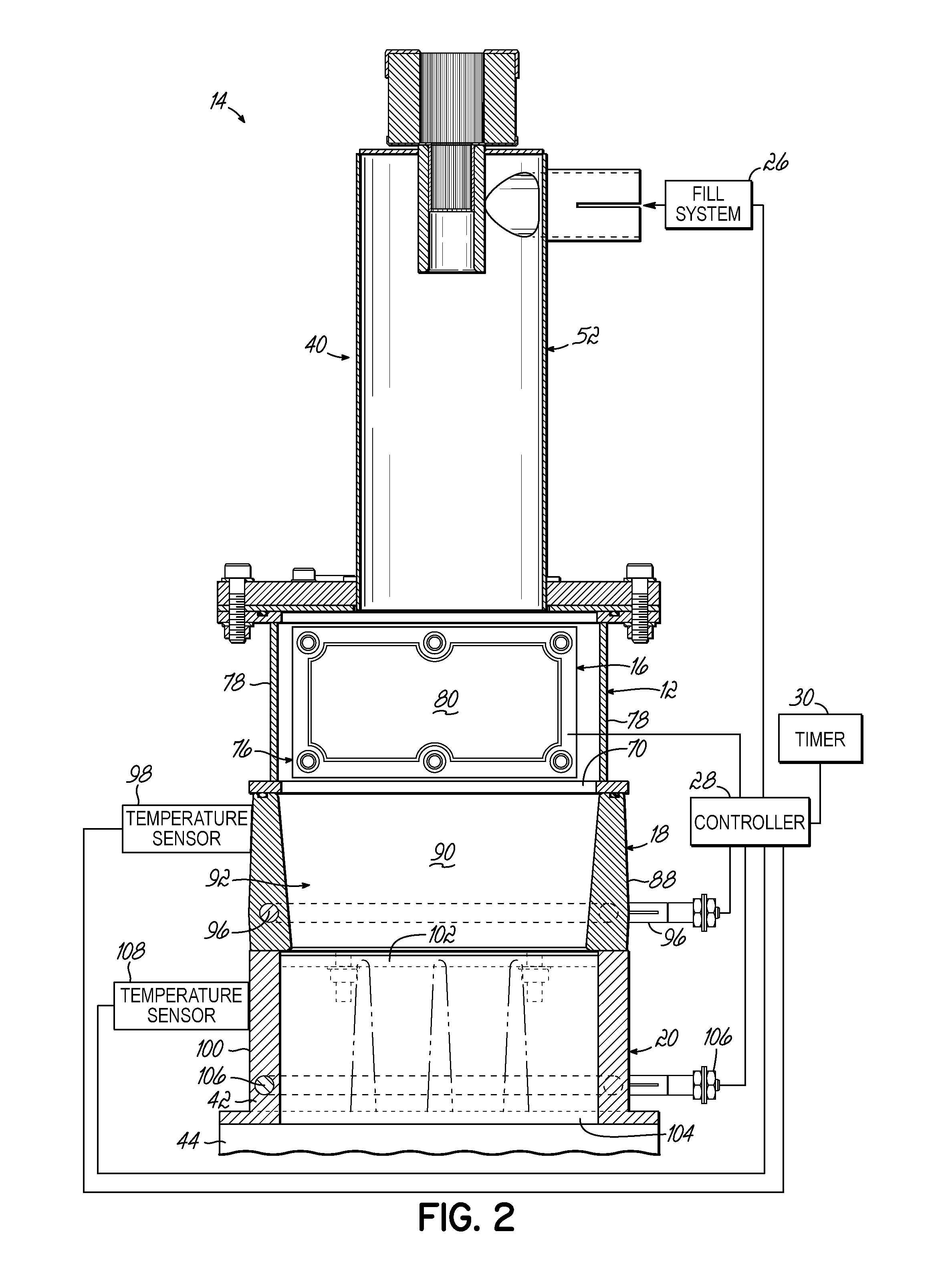
[0026]Referring to FIGS. 1 and 2, an adhesive dispensing system 10 in accordance with one embodiment of the invention is shown. The adhesive dispensing system 10 is configured to optimize the dispensing operation by using a smart melt heater control process to reduce the temperature of hot melt adhesive held within the dispensing system 10 during periods of low throughput. This reduction of temperature is automatically actuated based on the frequency of refilling a hopper 12 within the dispensing system 10, thereby significantly reducing the rate of degradation of the adhesive during the periods of low throughput. Moreover, unlike a standby mode procedure which requires a lengthy warm-up time to return to dispensing operations, the reduction in temperature of the adhesive caused by the smart melt heater process is tailored to enable rapid or immediate warm-up to dispensing operations after a reduction in temperature. In addition, the standby mode may still be used after a long perio...


PUM


Abstract

An adhesive dispensing system is configured to automatically reduce the temperature of adhesive material to reduce degradation of the adhesive caused by holding the adhesive at an application temperature during periods of low throughput. To this end, a controller of the system operates a heater unit to maintain a unit set point temperature to heat and melt adhesive until a set threshold time has elapsed since the most recent supply of adhesive to the system by a fill system. Once the time elapsed since the most recent supply of adhesive exceeds the set threshold time, the heater unit is reduced in temperature to reduce the temperature of adhesive. This reduction is temperature is large enough to minimize degradation and outgassing but small enough to enable rapid warm-up times after a new supply of adhesive occurs.

Description

CROSS-REFERENCE TO RELATED APPLICATION[0001]This application claims the benefit of U.S. Provisional Patent Application Ser. No. 61 / 718,311, filed on Oct. 25, 2012 (pending), the disclosure of which is incorporated by reference herein in its entirety.FIELD OF THE INVENTION[0002]The present invention generally relates to an adhesive dispensing system, and more particularly, to control components and methods used with heater units that melt adhesive in the adhesive dispensing system.BACKGROUND[0003]A conventional dispensing system for supplying heated adhesive (i.e., a hot-melt adhesive dispensing system) generally includes an inlet for receiving adhesive materials in solid or liquid form, a heater grid in communication with the inlet for heating and / or melting the adhesive materials, an outlet in communication with the heater grid for receiving the heated adhesive from the heated grid, and a pump in communication with the heater grid and the outlet for driving and controlling the disp...

Claims


Application Information

Patent Timeline
Patent Type & Authority Applications(United States)
IPC IPC(8): F16L53/00G01F23/26
CPCF16L53/00B05C11/1002Y10T137/0391Y10T137/6416B05C11/1042B05C11/1007
Inventor BONDESON, BENJAMIN J.ESTELLE, PETER W.HAND, KENT
Owner NORDSON CORP
Why Eureka
Try Eureka