Solarization-resistant borosilicate glass and use thereof for production of glass tubes and lamps and in irradiation units

a technology of solarization resistance and borosilicate glass, which is applied in the direction of electric discharge lamps, lighting and heating apparatus, instruments, etc., can solve the problems of unsuitable short-wave light transmission distribution, unsatisfactory results for many applications, and insufficient solarization resistan

Active Publication Date: 2014-05-01
SCHOTT AG
View PDF2 Cites 5 Cited by
  • Summary
  • Abstract
  • Description
  • Claims
  • Application Information

AI Technical Summary

Benefits of technology

[0015]According to the invention, a good solarization resistance is achieved, and the establishment of a defined position of the UV edge is possible, through a combination of the following three components: TiO2 0.05-0.4%; Mo030.025-0.3%; and V2O5 0.001-0.01%.
[0019]Preferably, the sum total of the alkali metal oxides in the components of the glass has a proportion of 5-6%, since this achieves a low coefficient of expansion, which promotes thermal cycling stability.
[0023]The inventive glass can be processed efficiently by the standard processes to give glass tubes, and is particularly suitable as a semi-finished product and for further processing to give lamp bulbs, shell tubes, but also for front panes and cover glasses.
[0026]For applications in which irradiation with ultraviolet wavelengths is as far as possible to be avoided or suppressed, glasses with a steep UV edge are usually desired. Such glasses move comparatively rapidly from the state of high transmission values to a state of very low transmission values at relatively short wavelengths. For lamps, irradiation units, weathering systems and the like, in which, however, it is desirable that a particular proportion of ultraviolet radiation penetrates through the glasses, the aim, in contrast, is a gradual transition from the state of high transmission to the blocking region and hence a flatter profile of the UV edge.

Problems solved by technology

However, this method is inconvenient and associated with corresponding costs, and leads to an unsatisfactory result for many applications, since the pre-aged glasses have a low transmission overall.
For particular applications, however, the distribution of the short-wave light transmitted is unsuitable, or the solarization resistance is inadequate.

Method used


Image

  • Solarization-resistant borosilicate glass and use thereof for production of glass tubes and lamps and in irradiation units
  • Solarization-resistant borosilicate glass and use thereof for production of glass tubes and lamps and in irradiation units
  • Solarization-resistant borosilicate glass and use thereof for production of glass tubes and lamps and in irradiation units

Examples


Embodiment Construction

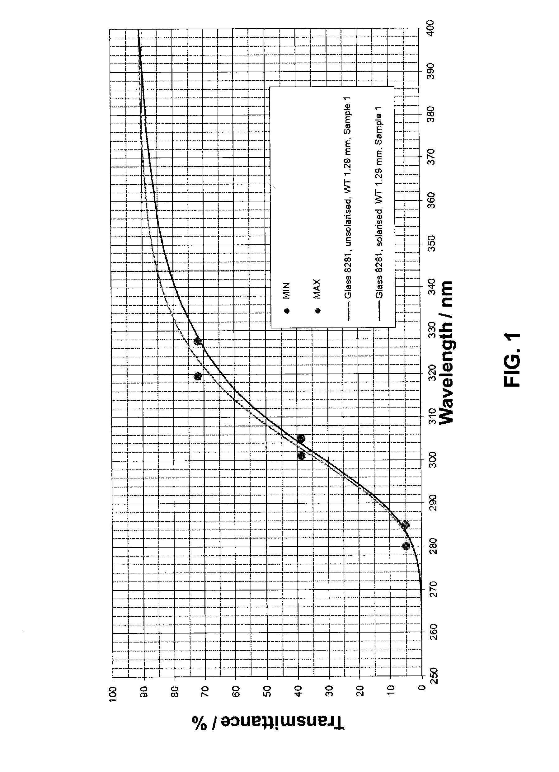
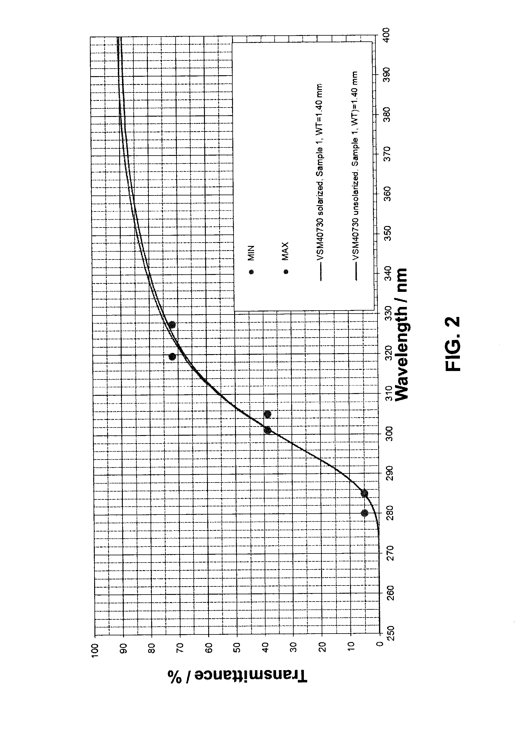
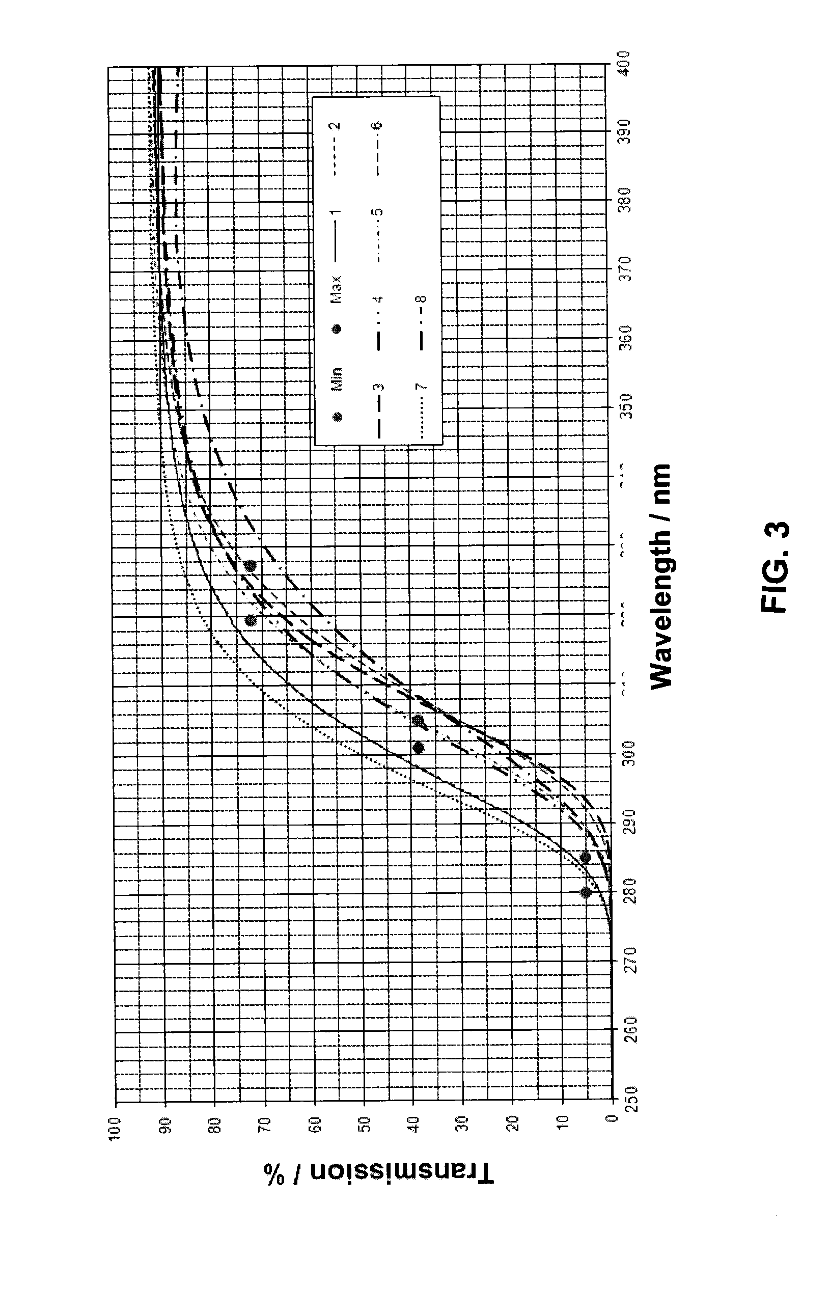
[0031]In FIGS. 1 to 3, for various glass samples, the profile of the transmission in percent was plotted over the wavelength range from 250 to 400 nm.

[0032]FIG. 1 shows the transmission profile of a glass sample according to the prior art (applicant's glass type 8281). The thickness of the glass sample was 1.29 mm. In the unirradiated state (the upper curve in FIG. 1), the transmission curve runs between the pairs of points for the target values, i.e. the specified transmission values are achieved at the desired wavelengths. The sample was irradiated with UV light from a UV radiator for a period of 15 hours. The UV radiator comprised a Philips HOK / 4 lamp (HOK 4 / 120 high-pressure mercury lamp). The distance of the lamp from the sample was 7 cm. The principal emission of the lamp was at 365 nm; the irradiation intensity at 200-280 nm at distance 1 m was 850 μW / cm2. The second curve shows the profile of the transmission curve after UV irradiation (the lower curve in FIG. 1). It is clea...


PUM

PropertyMeasurementUnit
wavelength rangeaaaaaaaaaa

Abstract

A borosilicate glass is provided that has high solarization resistance and a defined position of the UV edge. The borosilicate glass includes the following constituents, in percent by weight based on oxide, of:SiO2 65-85%;B2O3 7-20%;Al2O3 0-7%;Li2O 0-2%;Na2O 0-8%;K2O 0-12%;BaO 0-5%;CaO 0-2%;MgO 0-2%;ZnO 0-2%;TiO2 0.05-0.4%;MoO3 0.025-0.3%; andV2O5 0.001-0.01%.

Description

CROSS REFERENCE TO RELATED APPLICATIONS[0001]This application claims benefit under 35 U.S.C. §119(a) of German Patent Application No. 10 2012 219 614.5, filed Oct. 26, 2012, the entire contents of which are incorporated herein by reference.BACKGROUND OF THE INVENTION[0002]1. Field of the Invention[0003]The invention provides a borosilicate glass having good solarization resistance, and for the use thereof for the production of glass tubes and the production of lamps, and for the use thereof in irradiation units, for example as top glass, a front pane or a shell tube. Solarization is understood to mean the decline in transparency for light of various wavelength ranges, which is caused by the action of short-wave ultraviolet (UV) radiation. In the broadest sense, the ultraviolet radiation range is understood to mean the wavelength range below that of visible light (about <380 namometers (nm)). In the narrower sense of this invention, the UV range is regarded as the wavelength range...

Claims


Application Information

Patent Timeline
Patent Type & Authority Applications(United States)
IPC IPC(8): C03C4/08C03C3/091C03C3/093C03C3/089
CPCC03C4/085C03C3/089C03C3/091C03C3/093H01J61/302C03C3/11C03C4/0085F21V3/04H01J61/30H01K1/28
Inventor KASS, CHRISTOF
Owner SCHOTT AG
Why Eureka
Try Eureka