
Dynamic Tuning for Wave Energy Conversion

a wave energy conversion and dynamic tuning technology, applied in the direction of sea energy generation, engine control, buoyancy control, etc., can solve the problems of not considering the effect of added mass, unable to adjust to long periods, and the pendulum is of conventional design

Active Publication Date: 2014-05-01
GREGORY BRUCE
View PDF3 Cites 25 Cited by
  • Summary
  • Abstract
  • Description
  • Claims
  • Application Information

AI Technical Summary

Benefits of technology

The patent describes the use of high-strength materials, such as fiber-reinforced polymer (FRP) or aluminum alloys, to create structures with extra strength and stiffness. By orienting the fibers in the material, the resulting structures have strength in a required direction. The patent also discusses the use of ratchet wheels and reversing gears to deliver power to the flywheel in both directions. The technical effects of this invention include improved strength and stiffness of structures and the ability to deliver power to the flywheel in both directions.

Problems solved by technology

The pontoons are flat-bottomed, creating a large invariant added mass MOI that makes wide-range tuning impossible.
But Beane does not consider the effect of added mass.
The pendulum is of conventional design and therefore cannot be tuned to long periods without an impractically large superstructure.
Again the large invariant added mass MOI makes wide range tuning impossible.
In the cases listed above, the resonant period is dominated by a large fixed mass MOI and a large fixed added mass MOI and it is not possible to tune dynamically to the range of periods that characterize energetic ocean swells.
The implication is that when wave height is varying, tuning to the swell period may be difficult or impossible.
A drawback of Gregory's method is that it relies for tuning on variation in draft, which is achieved by pumping large volumes of seawater.

Method used


Image

  • Dynamic Tuning for Wave Energy Conversion
  • Dynamic Tuning for Wave Energy Conversion
  • Dynamic Tuning for Wave Energy Conversion

Examples


Embodiment Construction

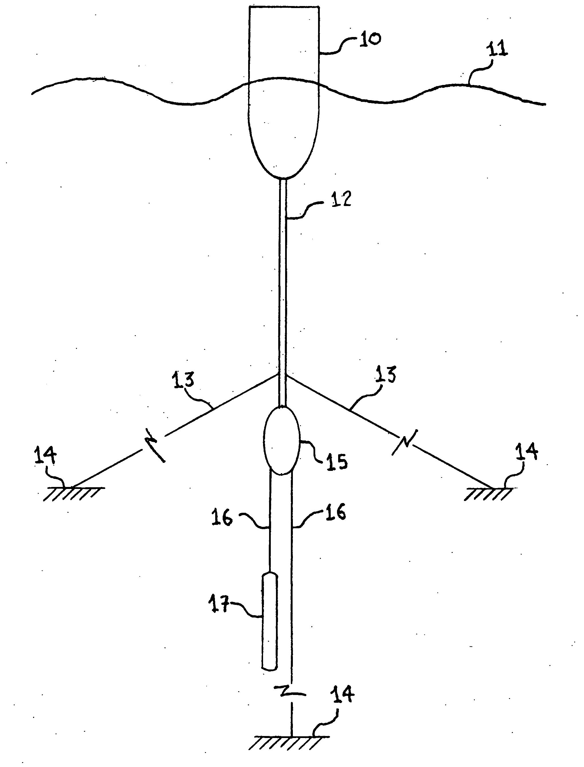
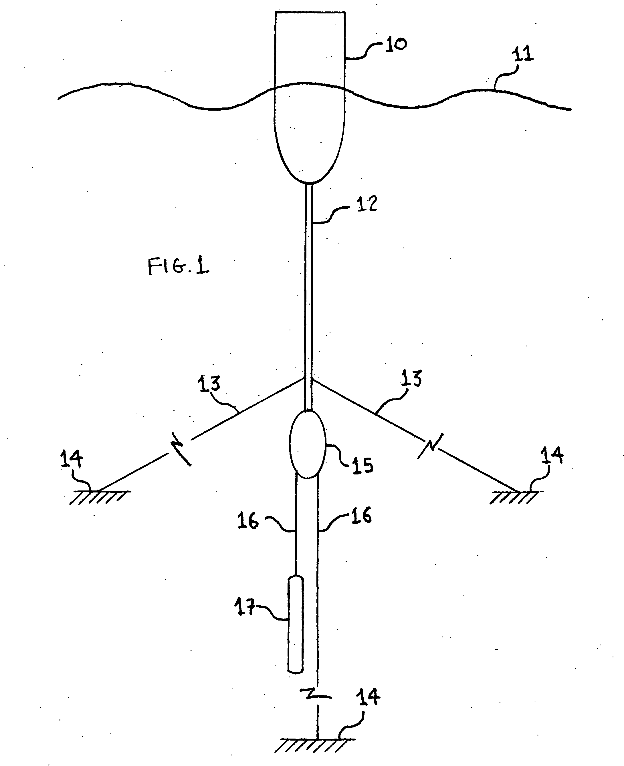
[0190]FIG. 1: side view of a heaving body with oscillating shaft generator

[0191]A LAM heaving body (10) floats in a swell (11). The bottom of the body (10) at the vertical axis is fixed to a rigid vertical rod (12). Connected to the rod (12) are at least three slack mooring lines (two are shown: 13) arranged at equal radial angles (not shown). The lines (13) are fixed to the seabed (14). Fixed to the bottom of the rod (12) is a LAM pod (15) containing an OSG (not shown). The OSG is driven by a cable (16) that loops round a wheel (not shown) on the OSG shaft (not shown). The cable is fixed to the seabed (14) at one end and to a counterweight (17) at the other end.

[0192]The mooring arrangement permits the body (10) to heave. As it does so the cable (16) reciprocates and the OSG generates electrical power.

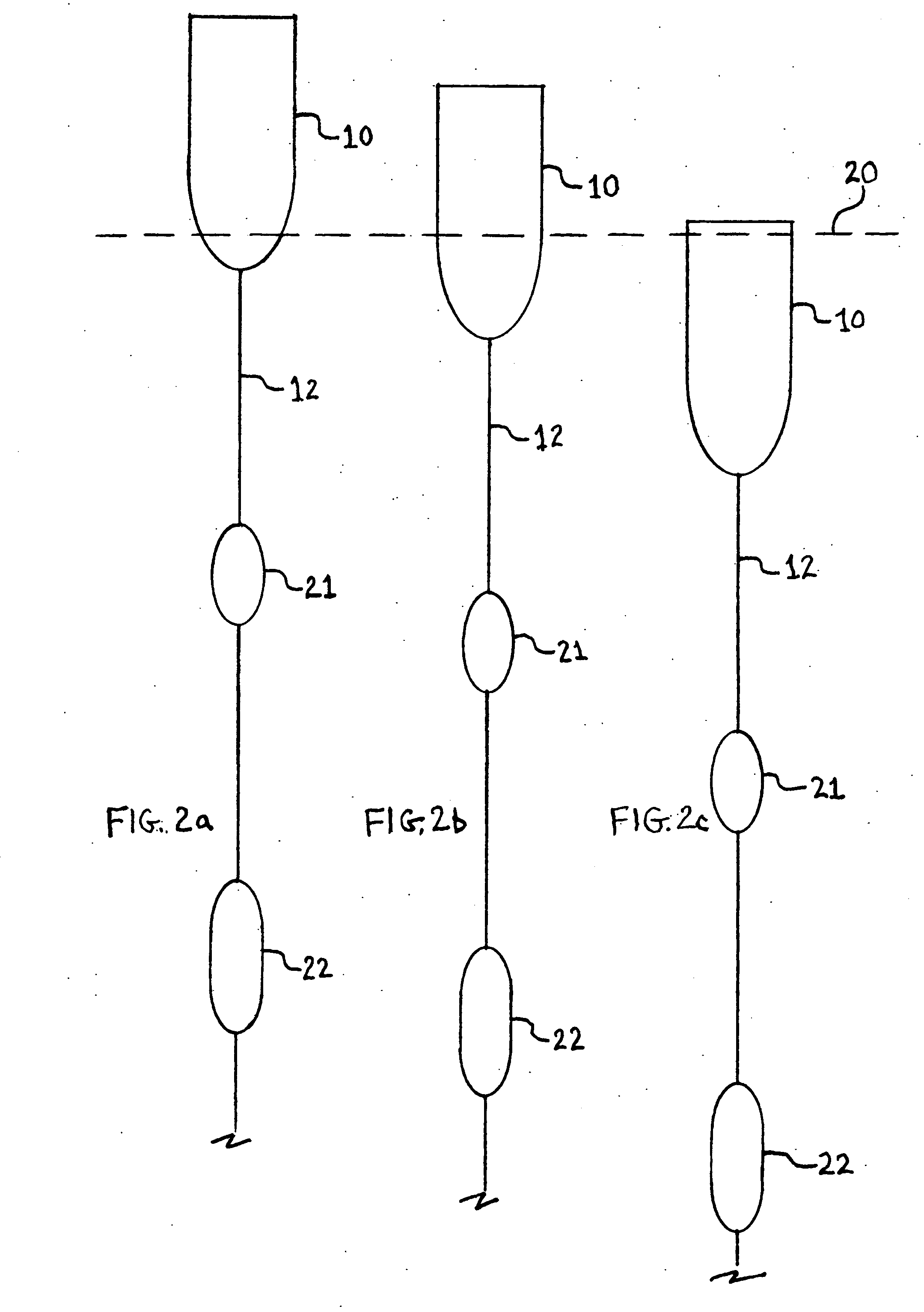
[0193]FIGS. 2a to 2c: side views of a heaving body that is tuned by locking and unlocking masses.

[0194]FIG. 2a: a LAM heaving body (10) rides substantially above the waterline (20). T...


PUM


Abstract

Wave energy converter efficiency is improved by dynamic tuning over periods from 5 to 15 seconds. Tuning methods are: for heaving, mass is varied by locking and unlocking neutrally buoyant masses or by trapping and releasing seawater; for surging, water-plane area is varied by force; for rotational variants of heaving and surging and for pitching, the radius of gyration is varied. Fixed mass is reduced by using materials and structures with high ratios of strength to weight. Fixed added mass is reduced by streamlining, by constant radius body profiles and by keeping moving structures out of the water. Added mass is varied continuously by using variable angle fins: effectiveness is enhanced by enclosure. In pitching, wave-bridging is addressed by limiting length, using locking and unlocking segments of the floating body or by using gravity as the restoring force. Solutions are described for heaving, surging, pitching and wave-following.

Description

RELATED APPLICATIONS[0001]This application references UK patent application GB 1116881.2 and U.S. patent application Ser. No. 13 / 407,888.FIELD OF INVENTION[0002]Oceanic wave energy conversion.BACKGROUND OF THE INVENTION[0003]Large amounts of wave energy are potentially available, with especially favorable locations in, for example, the UK, Ireland, the USA, Australia and New Zealand. Wave energy can be produced with low carbon emissions and can be part of the solution to the risks of global warming.[0004]There has been much interest in wave energy. Around 1,500 wave energy patents have been published worldwide over the last 100 years. Around 50 companies worldwide are trying to develop wave power. So far there has been no successful commercial megawatt-scale generation of power from waves.[0005]The main obstacles to such implementation are poor reliability, high cost, low efficiency and environmental impact.[0006]Reliability and cost problems arise from the oceanic environment, whic...

Claims


Application Information

Patent Timeline
Patent Type & Authority Applications(United States)
IPC IPC(8): F03B13/22
CPCY02E10/38F05B2270/18F03B13/16F03B13/22F03B13/20Y02E10/30F05B2270/202
Inventor GREGORY, BRUCE
Owner GREGORY BRUCE
Learn More