Antenna and filter structures

a filter and antenna technology, applied in the direction of slot antennas, waveguide devices, electrical equipment, etc., can solve the problems of large loss, large loss, and product becoming either too heavy or too expensive to be deployed on a large scal

Inactive Publication Date: 2014-05-01
MESAPLEXX
View PDF0 Cites 14 Cited by
  • Summary
  • Abstract
  • Description
  • Claims
  • Application Information

AI Technical Summary

Benefits of technology

[0011]According to one aspect, an embodiment of the invention provides a combined filter and antenna structure comprising a multi-mode cavity filter and an antenna. The filter comprises a dielectric body provided with a conductive covering and an interface arranged to exchange energy between a standing wave in the body and a current conveyed external to the body. The antenna is arranged to exchange energy between a travelling wave outside the body and a standing wave inside the body. The antenna comprises a first window provided in the covering. Structures formed in this way can compactly combine filtering and antenna operations.

Problems solved by technology

In particular, duplex filters, used in many handsets, will typically employ this form of filter technology and some higher power applications exist, although the high losses associated with commercial products typically restrict their use to power levels of a few watts (mean power) or less.
This process will typically result in a significant increase in the loss in the (wanted) pass-band, due to both the insertion loss of the dielectric material itself (i.e. the dielectric losses within that material) and the coupling losses in transferring energy into and out of the dielectric.
In contrast, a transmission line filter (e.g. a comb line or inter-digital filter) generally concentrates current in a relatively small conductor and hence has generally higher losses.
Unless small, low-cost, low-loss filters are used, the product becomes either too heavy or too expensive to be deployed on a large scale.
This connection, despite its short length, will incur losses, both due to mismatches of the various impedances involved (such mismatches are not caused by design, but result from imperfections in the manufacturing processes of the various components and materials involved) and due to the non-zero resistance of the conductors used.
For example, there will be a mismatch between the coupling structure used on the puck (i.e. a conductive interface on the puck for passing signals into and / or out of the puck) and the PCB upon which the puck is mounted, together with losses in the PCB tracks; there will also be losses in connecting this PCB to the PCB upon which the antenna element is formed (if it is a patch antenna) or the coaxial (or other transmission line) connection to a formed metal antenna structure (e.g. a dipole).
Even the radiating element itself will have a non-zero resistivity and hence some loss.
These losses will degrade both transmit EIRP and receive sensitivity (noise figure) of an antenna system and reduce its coverage area.

Method used


Image

  • Antenna and filter structures
  • Antenna and filter structures
  • Antenna and filter structures

Examples


Embodiment Construction

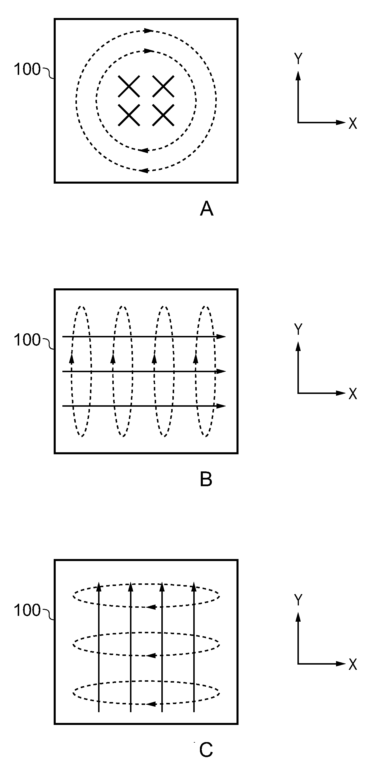
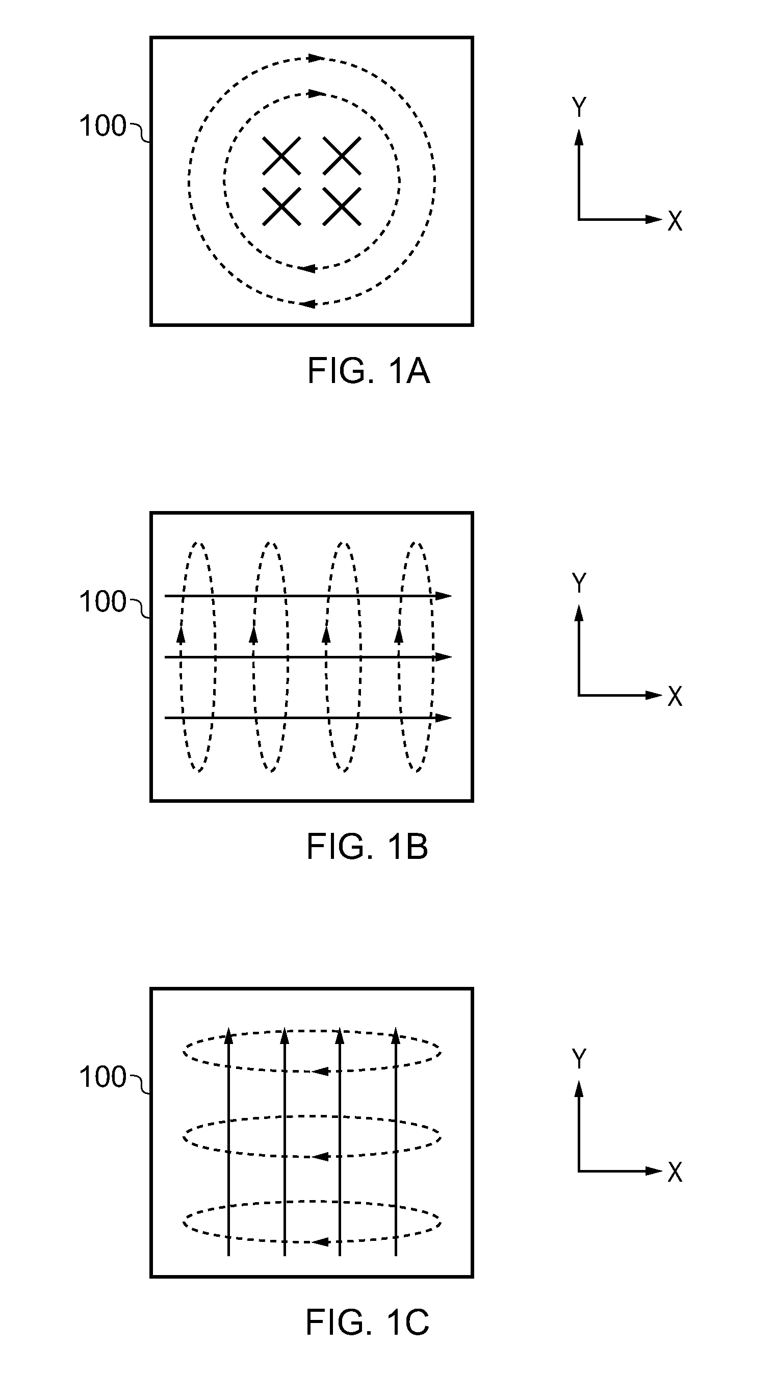
[0034]FIG. 3 shows a type of multi-mode filter. The filter 300 shown in FIG. 3 comprises a cubic puck 310 of ceramic dielectric with an applied metallisation 312. In FIG. 3, the metallisation on the nearest face of the puck and the puck itself have been shown as transparent so that various features pertaining to the metallisation can be seen and therefore described more easily. For the avoidance of doubt, however, the metallisation 312 extends completely over the nearest face of the puck and is continuous with the metallisation on the adjacent faces of the puck. This concept of treating the puck 310 and the metallisation 312 as transparent will be extended to FIGS. 3 to 11.

[0035]Given that the puck 310 is a cube, standing waves can be established in the puck in three distinct orientations. In each orientation, the electric field vector of the standing wave is parallel to the an edge of the cubic puck 310. The edges of the puck 310 can be thought of as running in orthogonal X, Y and ...


PUM


Abstract

A combined filter and antenna structure comprising a multi-mode cavity filter and an antenna, wherein: the filter comprises: a dielectric body provided with a conductive covering; and an interface arranged to exchange energy between a standing wave in the body and a current conveyed external to the body; and the antenna is arranged to exchange energy between a travelling wave outside the body and a standing wave inside the body and the antenna comprises: a first window provided in the covering.

Description

FIELD OF THE INVENTION [0001]The invention relates to filters and antennas for processing electrical signals.BACKGROUND [0002]Single mode dielectric filters are in widespread use in many communications systems, including both low and high-power use within the cellular communications industry. In particular, duplex filters, used in many handsets, will typically employ this form of filter technology and some higher power applications exist, although the high losses associated with commercial products typically restrict their use to power levels of a few watts (mean power) or less.[0003]In order to achieve a steep roll-off and a wide pass-band bandwidth in a dielectric filter design, it is typically necessary to cascade a number of dielectric resonators in series. This process will typically result in a significant increase in the loss in the (wanted) pass-band, due to both the insertion loss of the dielectric material itself (i.e. the dielectric losses within that material) and the co...

Claims


Application Information

Patent Timeline
Patent Type & Authority Applications(United States)
IPC IPC(8): H01Q13/18
CPCH01P1/2086H01P7/06
Inventor HENDRY, DAVID ROBERTCOOPER, STEVEN JOHNKENINGTON, PETER BLAKEBOROUGH
Owner MESAPLEXX
Why Eureka
Try Eureka