Components with micro cooled coating layer and methods of manufacture

Active Publication Date: 2014-05-01
GENERAL ELECTRIC CO
View PDF12 Cites 13 Cited by
  • Summary
  • Abstract
  • Description
  • Claims
  • Application Information

AI Technical Summary

Benefits of technology

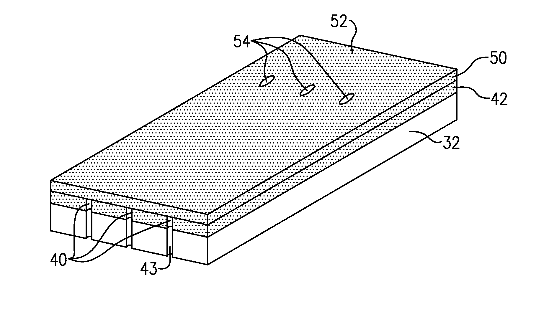
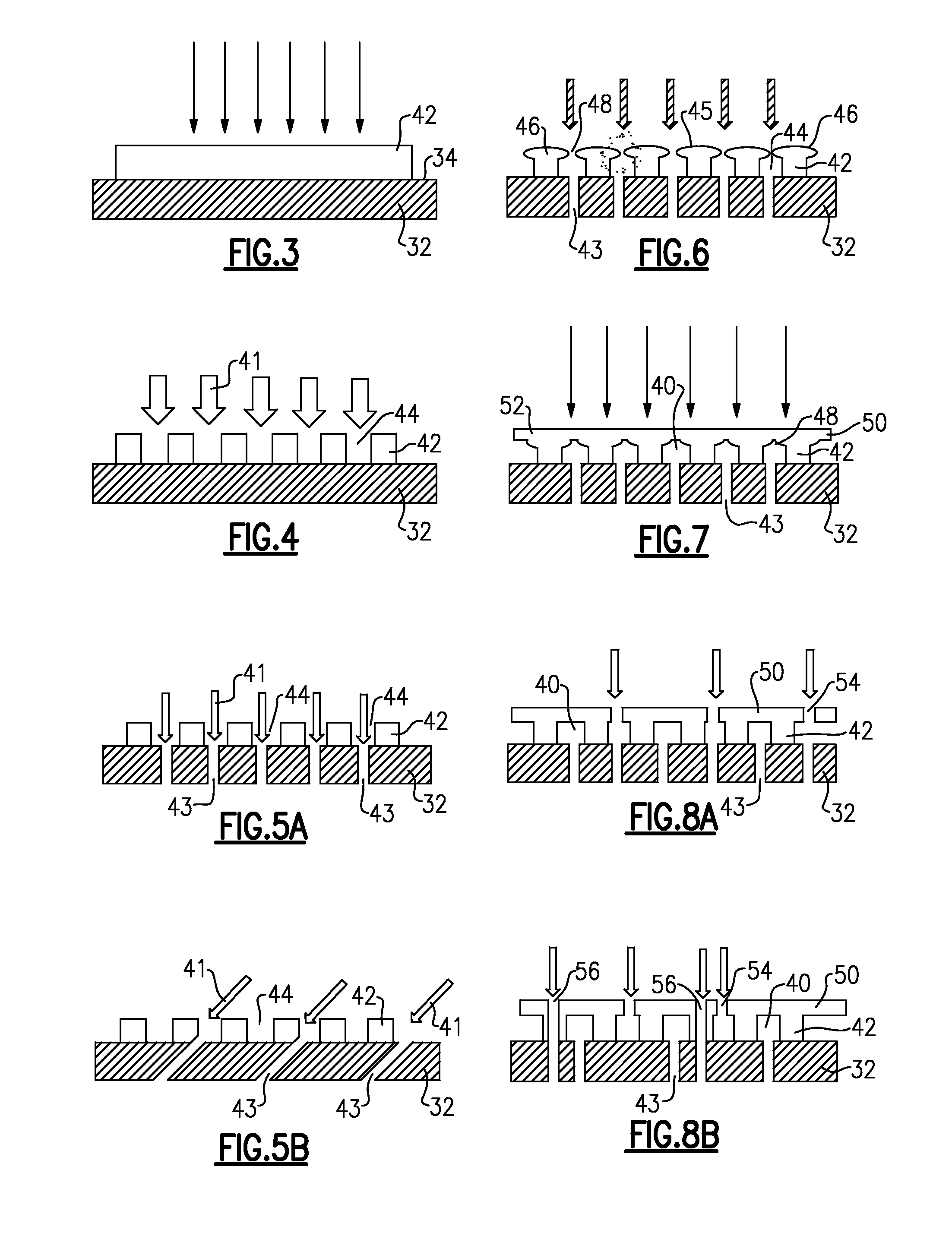
[0008]One aspect of the present disclosure resides in a manufacturing method that includes providing a substrate with an outer surface and at least one interior space; applying a coating on at least a portion of the substrate; forming one or more grooves in the coating wherein each groove extends at least partially along the coating; processing at least a portion of a surface of the coating so as to plastically deform the coating at least in a vicinity of the top of a respective groove, such that a gap across a top of the groove is reduced; and applying one or more additional coatings over at least a portion of the surface of the coating, wherein the substrate, the coating and the additional coating define one or more channels for cooling a component.
[0009]Another aspect of the present disclosure resides in a manufacturing method that includes providing a substrate with an outer surface and at least one interior space; applying a structural coating on at least a portion of the substrate; forming one or more grooves in the coating wherein each groove extends at least partially along the coating; processing at least a portion of a surface of the coating so as to plastically deform the coating at least in a vicinity of the top of a respec

Problems solved by technology

However, the combustion gases heat the various components along their flowpath, which in turn requires cooling thereof to achieve an acceptably long engine lifetime.
This cooling process reduces engine efficiency, as the bled air is not used in the combustion process.
However, this cooling strategy typically results in comparatively inefficient heat transfer and non-uniform component temperature profiles.
The filling of the channels with a fugitive material, and the later removal of that material present

Method used


Image

  • Components with micro cooled coating layer and methods of manufacture
  • Components with micro cooled coating layer and methods of manufacture
  • Components with micro cooled coating layer and methods of manufacture

Examples


Example

[0026]The terms “first,”“second,” and the like, herein do not denote any order, quantity, or importance, but rather are used to distinguish one element from another. The terms “a” and “an” herein do not denote a limitation of quantity, but rather denote the presence of at least one of the referenced items. The modifier “about” used in connection with a quantity is inclusive of the stated value, and has the meaning dictated by context, (e.g., includes the degree of error associated with measurement of the particular quantity). In addition, the term “combination” is inclusive of blends, mixtures, alloys, reaction products, and the like.

[0027]Moreover, in this specification, the suffix “(s)” is usually intended to include both the singular and the plural of the term that it modifies, thereby including one or more of that term (e.g., “the passage hole” may include one or more passage holes, unless otherwise specified). Reference throughout the specification to “one embodiment,”“another ...


PUM

PropertyMeasurementUnit
Lengthaaaaaaaaaa
Lengthaaaaaaaaaa
Diameteraaaaaaaaaa

Abstract

A manufacturing method includes providing a substrate with an outer surface and at least one interior space, applying a coating on a portion of the substrate and forming one or more grooves in the coating, wherein each groove extends at least partially along the coating. The method further includes processing at least a portion of the surface of the coating to plastically deform the coating in the vicinity of the top of a respective groove. An additional coating is applied over at least a portion of the surface of the coating. A component is disclosed and includes a substrate, a coating disposed on at least a portion of the substrate, and defining one or more grooves therein, and an additional coating disposed over at least a portion of the coating. The substrate, the coating and the additional coating together define one or more channels for cooling the component.

Description

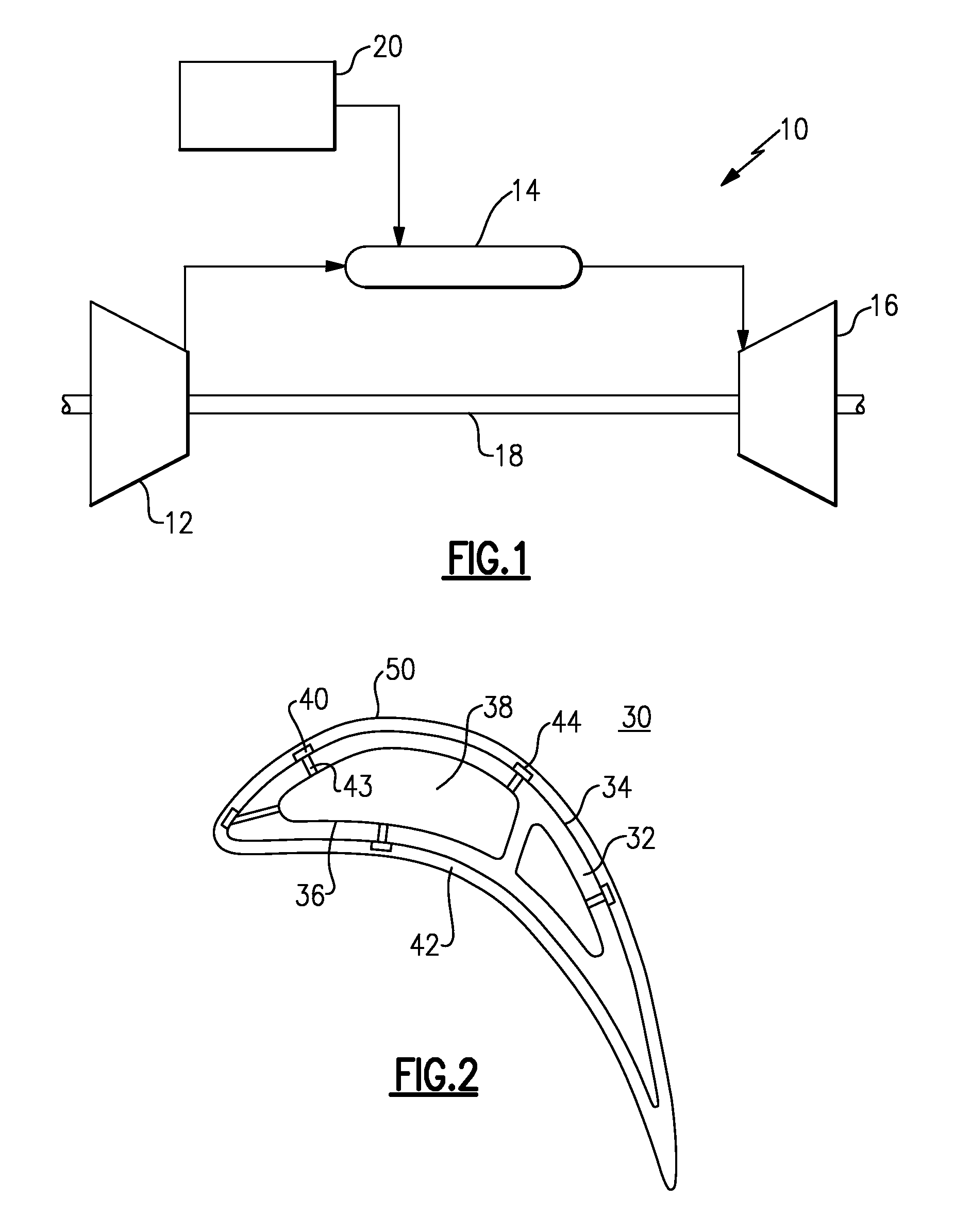
BACKGROUND[0001]The disclosure relates generally to gas turbine engines, and, more specifically, to micro-channel cooling therein.[0002]In a gas turbine engine, air is pressurized in a compressor and mixed with fuel in a combustor for generating hot combustion gases. Energy is extracted from the gases in a high pressure turbine (HPT), which powers the compressor, and in a low pressure turbine (LPT), which powers a fan in a turbofan aircraft engine application, or powers an external shaft for marine and industrial applications.[0003]Engine efficiency increases with temperature of combustion gases. However, the combustion gases heat the various components along their flowpath, which in turn requires cooling thereof to achieve an acceptably long engine lifetime. Typically, the hot gas path components are cooled by bleeding air from the compressor. This cooling process reduces engine efficiency, as the bled air is not used in the combustion process.[0004]Gas turbine engine cooling art i...

Claims


Application Information

Patent Timeline
IPC IPC(8): F01D5/18B05D3/06B05D3/12
CPCF01D5/18B05D3/06B05D3/12C23C4/18F01D5/288F01D5/184F01D5/187F05D2260/204C23C14/5886C23C4/073Y10T428/13Y02T50/60
Inventor BUNKER, RONALD SCOTTWEAVER, SCOTT ANDREW
Owner GENERAL ELECTRIC CO
Why Eureka
Try Eureka