Burner for exhaust purifying device

a technology of exhaust purification device and burner, which is applied in the direction of combustion types, machines/engines, lighting and heating apparatus, etc., can solve the problems of increasing fuel consumption, difficult ignition of fuel and air mixture, etc., and achieves the effect of easy burning

Inactive Publication Date: 2014-05-08
HINO MOTORS LTD
View PDF7 Cites 24 Cited by
  • Summary
  • Abstract
  • Description
  • Claims
  • Application Information

AI Technical Summary

Benefits of technology

[0027]According to the other aspect described above, the fuel is mixed with air in advance in the premixing chamber and supplied to the combustion region, and the suppli...

Problems solved by technology

As a result, the mixture of fuel and air becomes difficult to ignite compared to when the temperature in the burner is high.
This increases fuel consumption when the temperature of the filter is raised to the same extent.
Such a problem occurs not...

Method used


Image

  • Burner for exhaust purifying device
  • Burner for exhaust purifying device
  • Burner for exhaust purifying device

Examples


first embodiment

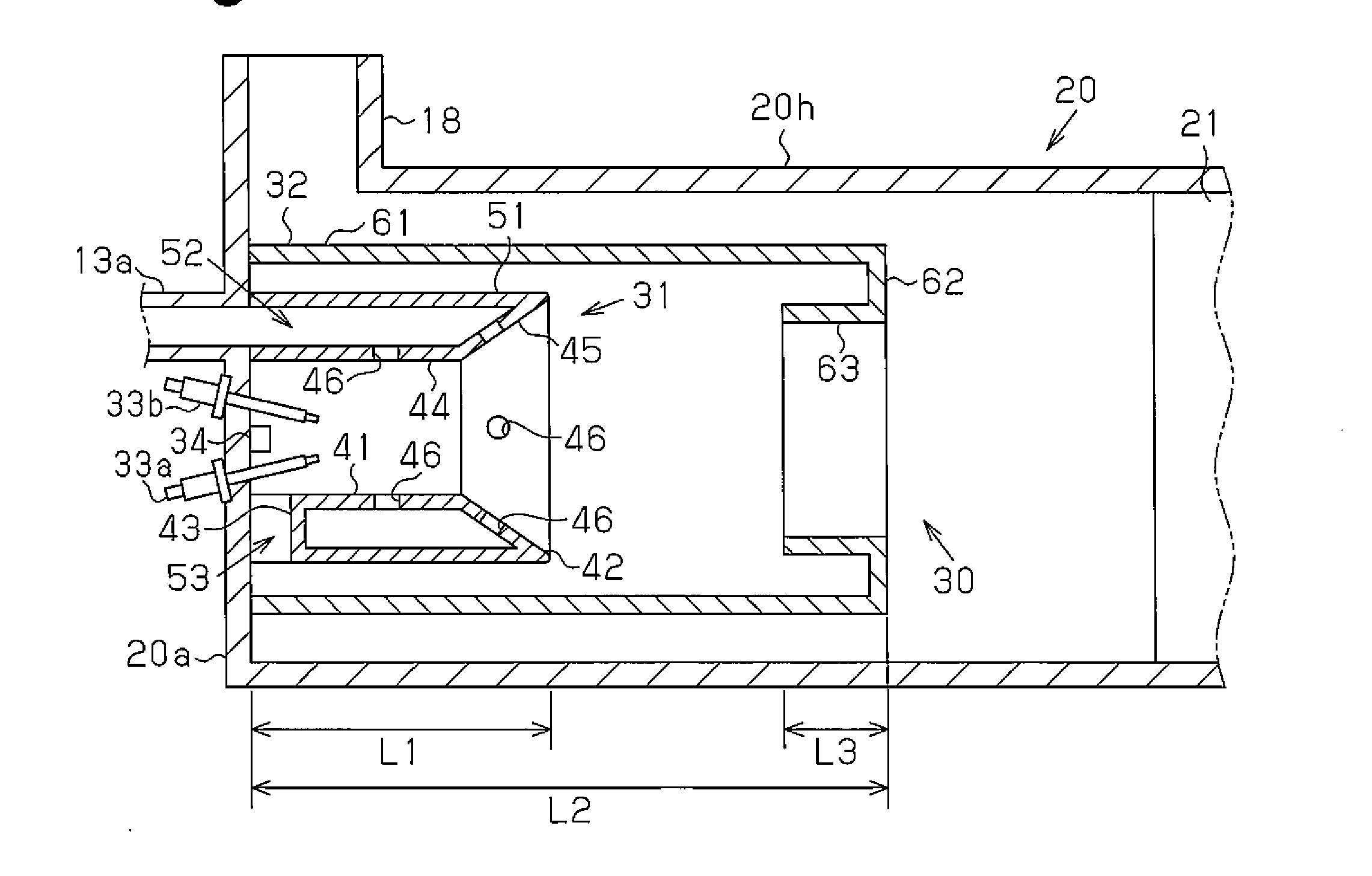
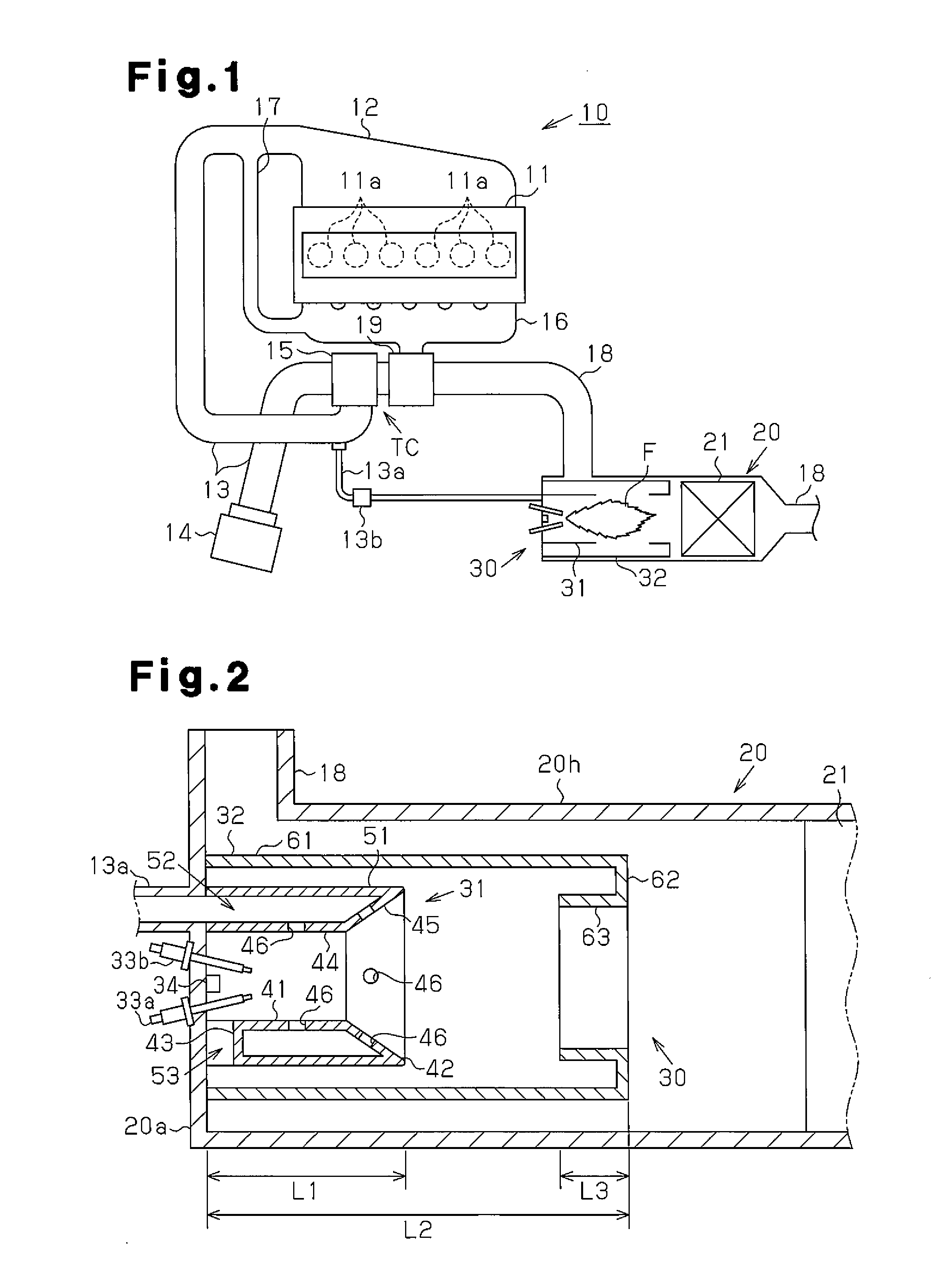
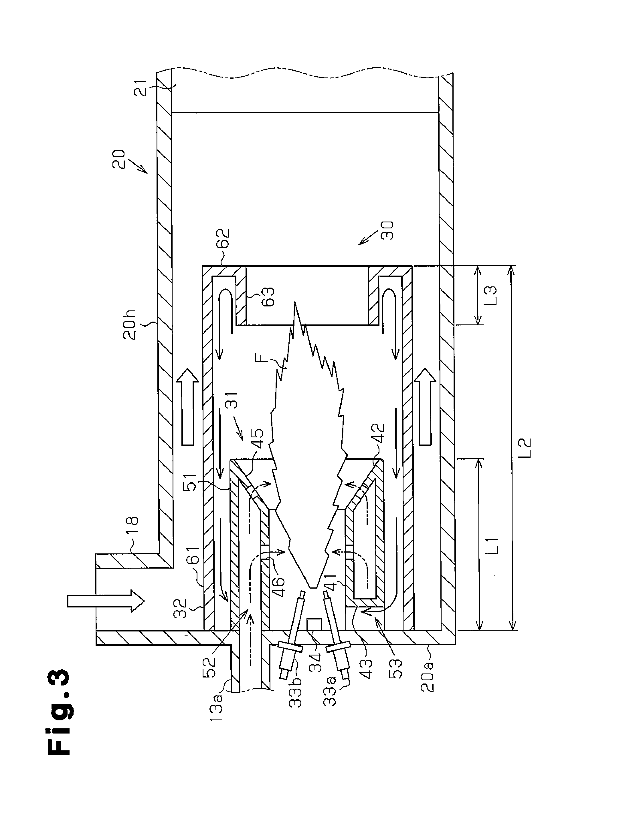
[0034]A first embodiment of a burner according to the present disclosure will now be described with reference to FIG. 1 to FIG. 3. First, the entire structure of a diesel engine including the burner will be described with reference to FIG. 1. The description will focus on a passage for the air drawn into the diesel engine and a passage of the exhaust discharged from the diesel engine, and other parts will not be described. Hereinafter, “upstream” and “downstream” are defined with respect to the direction in which air and exhaust flows in the diesel engine.

[0035][Schematic Structure of Diesel Engine]

[0036]As shown in FIG. 1, a cylinder block 11 of a diesel engine 10 includes six cylinders 11a arranging in a single row. An intake manifold 12, which supplies intake air to each cylinder 11a, and an exhaust manifold 16, into which the exhaust from each cylinder 11a flows, are connected to the six cylinders 11a.

[0037]An intake pipe 13, which is a passage for the intake air, is connected ...

second embodiment

[0078]A second embodiment of a burner according to the present disclosure will now be described with reference to FIG. 4 to FIG. 6. FIG. 5 shows a cross-sectional structure taken along line 5-5 in FIG. 4, and FIG. 6 shows a cross-sectional structure taken along line 6-6 in FIG. 4. The burner of the second embodiment differs from the burner of the first embodiment in the structure associated with the supply of fuel in the burner and the structure associated with the supply of air. Such differences will be described in detail below, and other parts will not be described.

[0079][Structure of Burner]

[0080]As shown in FIG. 4, a burner 70 includes a base body 70b formed to have the shape of a circular plate. The base body 70b is fixed to the basal end of the flame stabilizer 31, which is formed to be cylindrical. The recirculation unit 32 is arranged on the outer side of the flame stabilizer 31 with a gap formed with the flame stabilizer 31, and the basal end of the recirculation unit 32 i...


PUM


Abstract

A burner used in an exhaust purifying device that purifies exhaust in an exhaust pipe of a diesel engine is provided with a tubular flame stabilizer including an ejection port from which fluid generated through combustion is ejected. The flame stabilizer includes a connecting passage, which connects the interior of the flame stabilizer and the exterior of the flame stabilizer. A recirculation unit is arranged at an outer side of the flame stabilizer. The recirculation unit includes a flow receiving portion that receives the fluid ejected from the ejection port, and an outer guiding portion that guides the fluid received by the flow receiving portion to the connecting passage.

Description

CROSS-REFERENCE TO RELATED APPLICATIONS[0001]This application is a national stage application under 35 U.S.C. 371 and claims the benefit of PCT Application No. PCT / JP2013 / 064240 filed 22 May 2013, which designated the United States, which PCT Application claimed the benefit of Japanese Patent Application No. 2012-119897 filed 25 May 2011, the disclosure of each of which are incorporated herein by reference.FIELD OF THE INVENTION[0002]The technique of the present disclosure relates to a burner used in an exhaust purifying device that purifies exhaust from an engine with a filter or a catalyst.BACKGROUND OF THE INVENTION[0003]Patent document 1 describes an example of a widely used engine exhaust purifying device that captures particulates in the exhaust with a diesel particulate filter (hereinafter referred to as filter). In the exhaust purifying device, the particulates in the exhaust are captured with the filter to purify the exhaust. However, the particulates need to be removed fro...

Claims


Application Information

Patent Timeline
IPC IPC(8): F01N3/025
CPCF01N3/0253F23C7/002F23D11/24F23D11/402F23D11/406F23C2201/20F23C2900/06041F23C9/006F23G7/065F01N3/2033F01N2240/14Y02T10/12
Inventor SHIBUYA, RYOTSUMAGARI, ICHIRO
Owner HINO MOTORS LTD
Why Eureka
Try Eureka