Method and apparatus for the downhole injection of superheated steam

a superheated steam and downhole technology, applied in the direction of borehole/well accessories, drilling casings, drilling pipes, etc., can solve the problems of becoming increasingly difficult to raise oil to the surface, typically only able to recover approximately 20% of the original oil in place, etc., to speed up the recovery process and reduce the viscosity of oil

Inactive Publication Date: 2014-05-08
TRIMETEOR OIL & GAS CORP
View PDF13 Cites 2 Cited by
  • Summary
  • Abstract
  • Description
  • Claims
  • Application Information

AI Technical Summary

Benefits of technology

[0032]Fundamentally, it is an important object to continuously heat crude oil deposits deep within wells during extraction, to lower the viscosity of the oil, and to thus speed up the recovery process.

Problems solved by technology

It has long been recognized in the art that, when the natural drive energy of an oil reservoir or well decreases over time, it becomes increasingly difficult to raise oil to the surface.
However, it is typically only able to recover approximately 20% of the Original Oil in Place (OOIP), compared to steam flooding, which has been reported to recover over 50% of OOIP.

Method used


Image

  • Method and apparatus for the downhole injection of superheated steam
  • Method and apparatus for the downhole injection of superheated steam
  • Method and apparatus for the downhole injection of superheated steam

Examples


Embodiment Construction

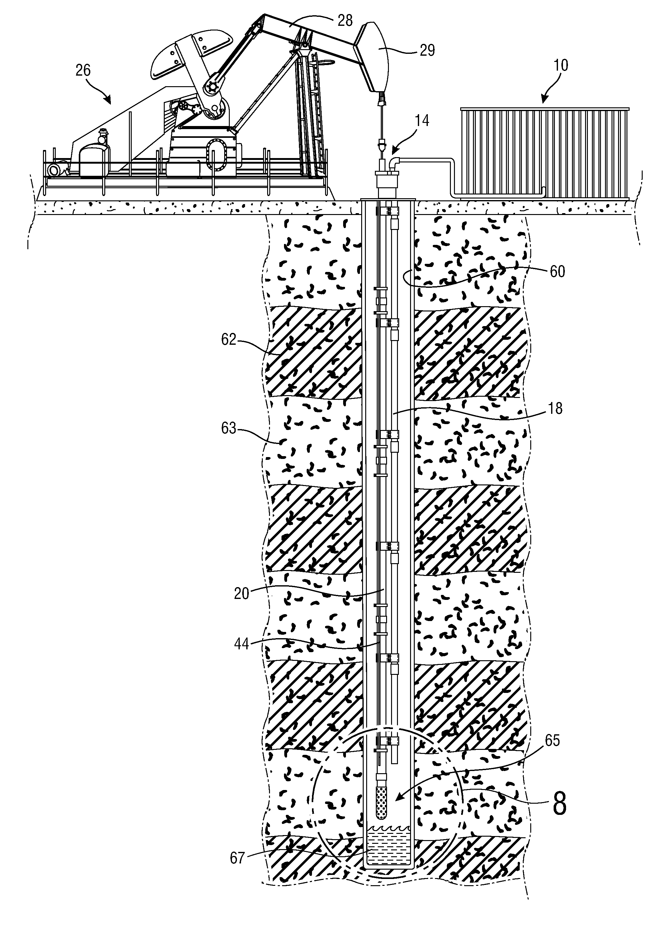
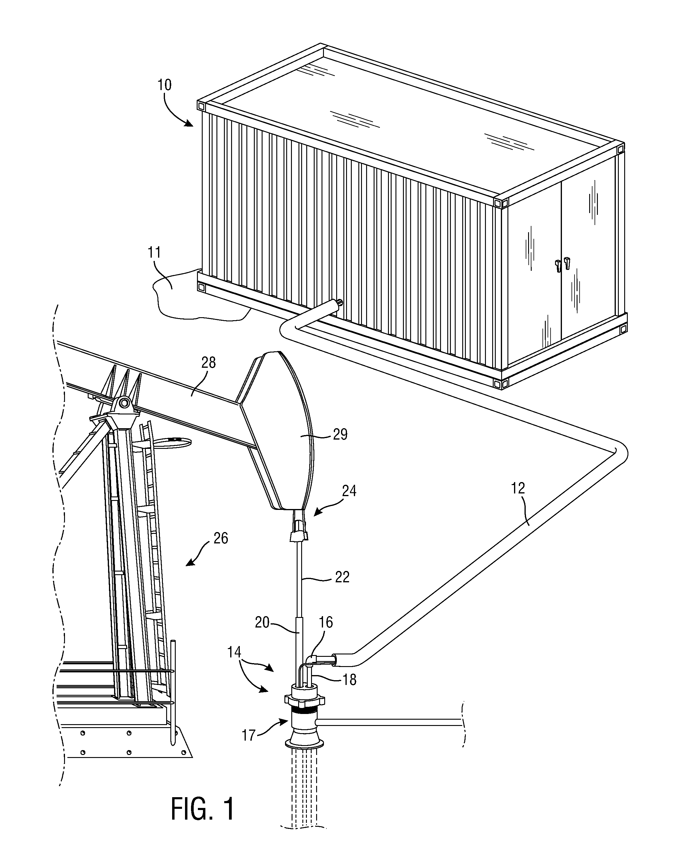
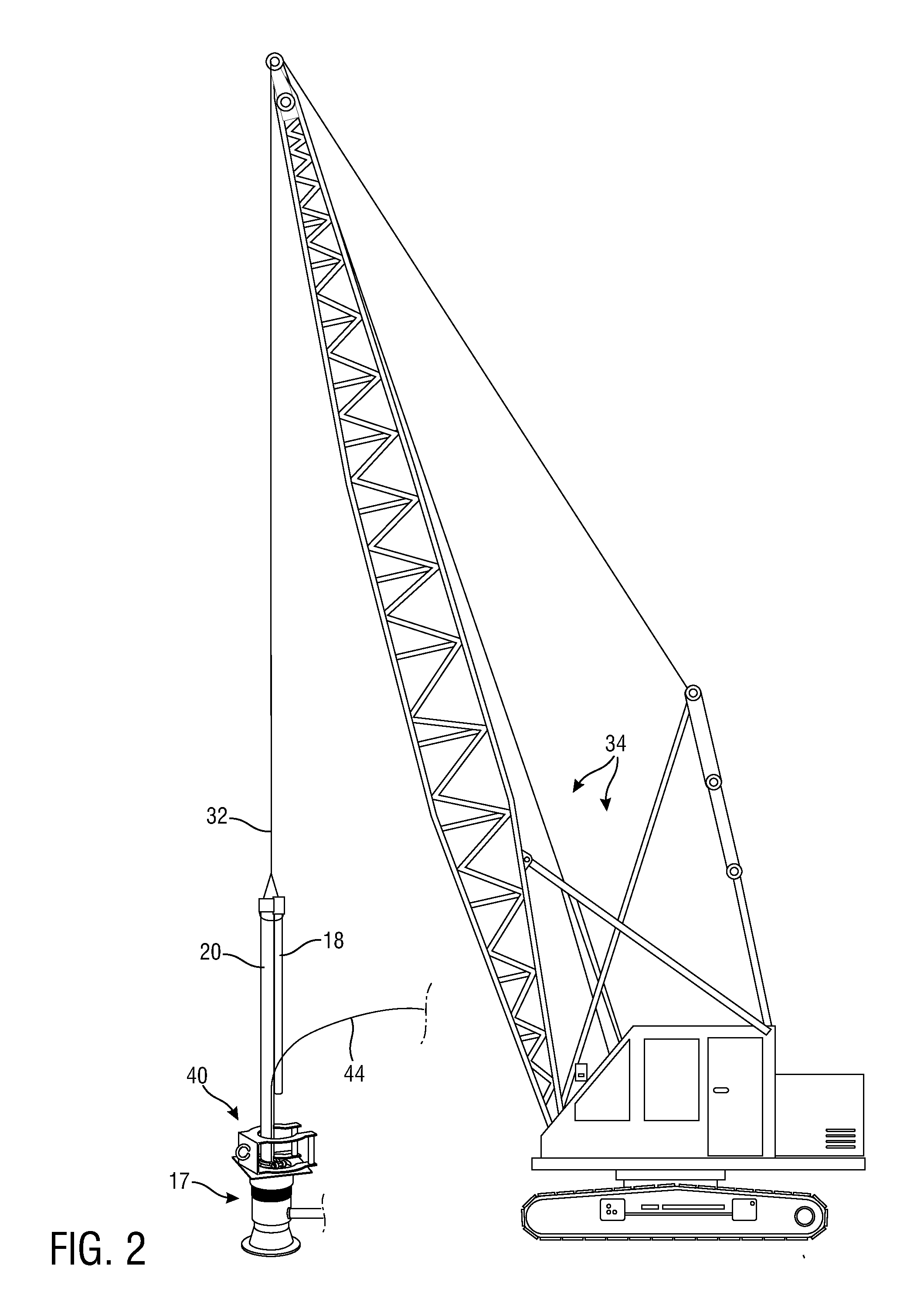
[0045]As is well recognized by those skilled in the art, steam generated through a variety of techniques can be injected into wells through various piping arrangements for secondary and tertiary oil recovery. With initial reference now directed to FIGS. 1 and 2 of the appended drawings, a high volume of superheated steam, preferably at a temperature between approximately 1000 degrees F. and 1600 degrees F., is produced and supplied by a steam generator, which has been generally designated by the reference numeral 10.

[0046]A suitable superheated steam generator is illustrated in our prior U.S. Pat. No. 8,358,919, issued Jan. 22, 2013, entitled “Super Heated Steam Generator With Slack Accommodating Heating Tanks,” the entire disclosure of which is hereby incorporated by reference as if fully set forth herein.

[0047]However, in the best mode known to us at this time, results obtained with the instant downhole injection teachings are maximized by supplying steam through the techniques an...


PUM


Abstract

Superheated steam from a generator (10) proximate a well (14) is delivered through an output pipe (12) that communicates through a dual entry wellhead (17) with downhole steam piping (18) extending into the well (14). Steam is delivered at approximately 50 PSIG over the frictional and other losses encountered from the surface to the steam piping outlet (19). Oil is extracted through production tubing (20) passing through wellhead (17). Production tubing (20) and steam delivery piping (18) are secured in parallel relationship by clamps (46). The production tubing (20) communicates with a lift pump, and the steam piping (18) is terminated generally at a midpoint of the production tubing (20), several feet above the lift pump. A thermocouple (43) is placed approximately two feet below the end of the steam piping (18).

Description

CROSS REFERENCE TO RELATED APPLICATION[0001]This utility patent filing is based upon and claims the effective filing date of a prior U.S. Provisional patent application entitled “Method and Apparatus for the Downhole Injection of Superheated Steam”, Ser. No. 61 / 721,618, filed Nov. 2, 2012, with coinventors Richard B. Graibus, Jimmy L. Turner, Charles T. McCullough, and Dennis K. Williams.BACKGROUND OF THE INVENTION[0002]1. Field of the Invention[0003]The present invention relates generally to the downhole delivery of superheated steam for recovering crude oil of low specific gravity, for enhancing reservoir drive, and for deparrafinization. More particularly, the invention relates to enhanced oil recovery methods and apparatus for subterraneously steam with a heat capacity consistent with 900 degrees F. of superheat, i.e., steam at a minimum temperature of 900 degrees F. above the saturation temperature of a water / steam mixture, at a pressure sufficient to overcome the frictional pr...

Claims


Application Information

Patent Timeline
Patent Type & Authority Applications(United States)
IPC IPC(8): E21B43/24
CPCE21B43/24E21B36/006E21B43/126
Inventor GRAIBUS, RICHARD B.TURNER, JIMMY L.MCCULLOUGH, CHARLES T.WILLIAMS, DENNIS K.
Owner TRIMETEOR OIL & GAS CORP
Why Eureka
Try Eureka